EasyCNC is a free, platform-independent solution for effectively managing CNC inventories and routers. It can easily be integrated into an existing workflow and leverages computer vision for digitizing used stock, and is capable of automatically generating highly optimal layouts for machining new parts. EasyCNC is intended for machining 2D parts on 3-axis CNC routers.
Supported Languages:
- English (UK, US) 🇬🇧 🇺🇸
- Chinese (Simplified, Traditional) 🇨🇳 🇹🇼
- Russian 🇷🇺
- Japanese 🇯🇵
An older, prototype version of the app can be found here: https://github.com/nagan319/NEXACut-Pro
- Installation
- How to Use
- App Structure and Functionality
- Screenshots and Demonstration
- FAQ
-
Make sure that you have Python and Git installed.
-
Run the following commands to execute the program:
git clone https://github.com/nagan319/EasyCNC.git
cd EasyCNC
pip install -r requirements.txt
python run.py
You should now see the following title screen:
The app is ready to run locally out of the box. By default, it is configured to create a SQLite3 database titled app_data.db in the src\data directory.
Using the app is fairly straightforward.
After you have opened the app, navigate to the 'Settings' menu and ensure that the correct units and language are selected. Note that the app must be restarted for new settings to be applied.
Add CNC routers by navigating to the 'Manage CNC Routers' tab, adding new routers, and configuring their parameters. After you have configured all parameters, hit 'Save' and you will see the router preview change to reflect your CNC router.
Note that all numerical input fields support both fractional input as well as input in alternate units ('in', 'feet', 'ft', 'mm', and 'cm').
Add CNC stock by navigating to the 'Manage Stock' tab and editing stock parameters. Hit save after you are done editing dimensions.
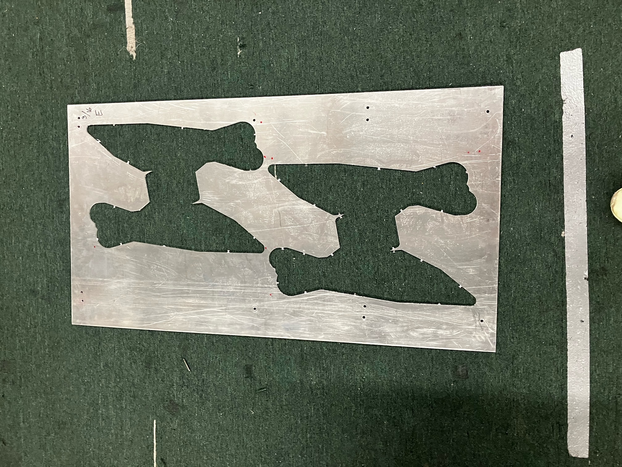
It is possible to digitize pre-used stock by importing an image of the stock and digitizing it using the app's built-in functionality. I would suggest laying out the stock on a contrasting surface and capturing an image from directly above the stock, making sure that reflections and shadows are kept to a minimum. The following is a good example:
If you would like to see additional examples of acceptable images, see the src\tests\test data\images directory. Do not delete or modify this directory, since it is referenced by various unit tests. Note that transparent stock may be harder to digitize - shining UV light or a similar approach may be a good idea.
After you have taken images for stock, make sure that the plate you would like to edit has your desired dimensions (the preview should be accurate), then hit 'Import Image'.
Import your desired image (note that HEIC format is not supported by OpenCV) and adjust the binary thresholding slider until the plate can be clearly distinguished from the background.
After you have thresholded the image, click 'Save Result'. The app's image processing algorithm will automatically identify any contours or plate corners. Note that detection is not 100% accurate and you may have to manually edit the image features.
The app will require you to add missing corners until the right amount (4) is reached. You can then select misplaced corners or unnecessary contours and delete them using the 'Delete' button. After features editing is complete, the image will be flattened and you will be shown the finalized contours. If you are satisfied, hit 'Save' and the stock will be updated.
After you have configured CNC stock and routers to match your inventory, you can import any CAD parts that you would like to machine.
Parts can be imported in STL format, which is easily obtainable in CAD software such as SolidWorks and Fusion. Make sure to download an ASCII STL file with millimeters as the unit.
Note that in order for CAD files to be handled correctly, they must consist solely of 2D shapes extruded to a certain uniform thickness and must be properly aligned along the X, Y, or Z axis. Also note that you should only import parts of a uniform material and thickness at one time, since layout optimization logic will require selecting plates with the same parameters.
After you have imported all desired parts, select all stock you would like to consider using for machining them, as well as the router you would like to use. You can select/unselect individual plates manually or select all plates with a certain material and thickness.
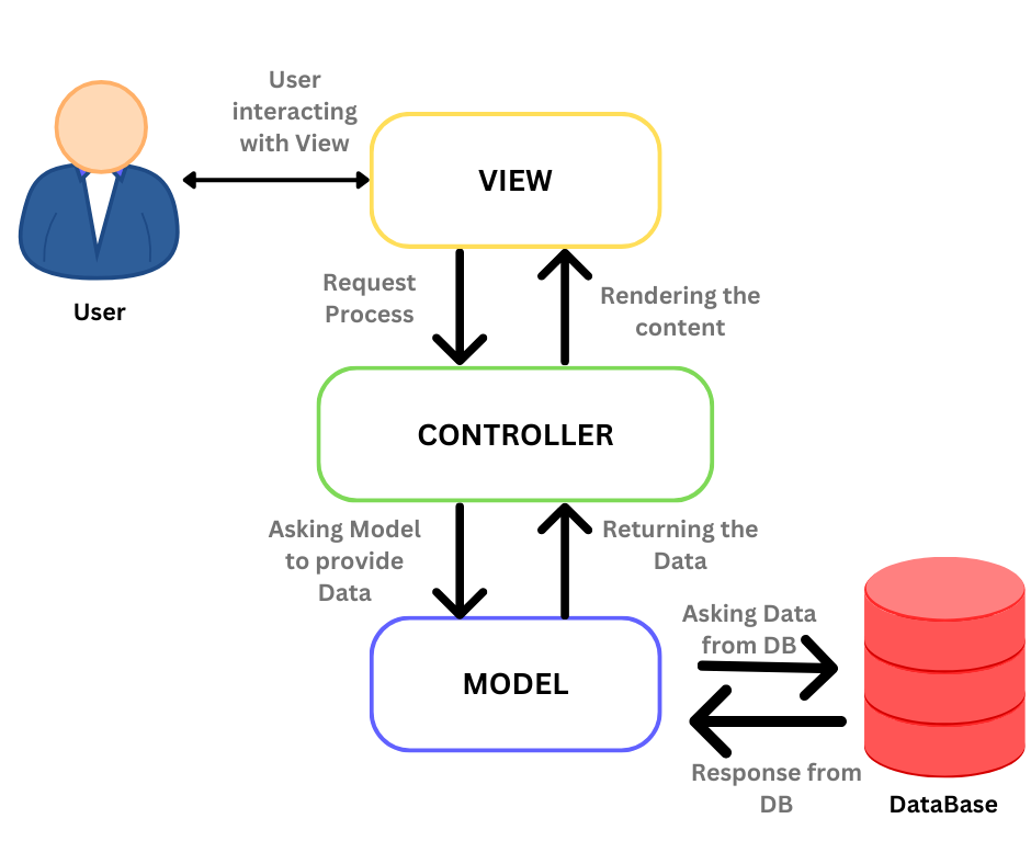
Image Source: https://medium.com/@sadikarahmantanisha/the-mvc-architecture-97d47e071eb2
The app follows a traditional MVC structure. The src/app directory is subdivided into the following directories and files:
Modules:
- controllers - Main logic handlers for interacting with database. Intermediate layer between UI and ORM models.
- models - SQLAlchemy ORM models for routers, plates, and imported parts, plus relevant utility functions
- resources - App fonts, stylesheets, images etc.
- utils - Various utility classes to handle image processing, layout optimization, STL parsing, plotting etc.
- views - High-level widgets for invidivual app screens
- widgets - lower-level widgets for custom displays etc.
Scripts:
- database - Small script to handle database initialization.
- load_settings - Retrieves user settings values at app initialization.
- logging - Initializes logging configuration.
- mainwindow - Modified Qt MainWindow class.
- styling - applies global fonts and stylesheets.
- translations - contains all app text and translations into supported languages.
There are additional directories for storing app data and logs, as well as a separate directory containing unit tests for backend logic.
The conversion process for CAD files follows a straightforward approach. Initially, it receives an STL file consisting of a list of facets with their respective points. The process identifies the axis with the fewest unique coordinates, assuming the CAD files are flat and parallel to a coordinate axis. It then 'flattens' the file by filtering out facets lying directly on the target plane, discarding unnecessary geometric data. Outside edges are then filtered out based on the fact that they, by definition, only belong to one facet.
I have chosen STL as the desired input format since it is significantly easier to deal with than formats such as .sldprt, has very little unnecessary features and can be parsed with existing libraries, and can easily be obtained by using built-in conversion tools in software such as Fusion360 and SolidWorks.
The image conversion process consists of four key stages, achieved via the OpenCV image processing library in Python. Initially, the raw image undergoes resizing and binary conversion via thresholding. Then, additional filtering is applied to reduce noise and refine the binary representation.
Next, a feature detection algorithm is used to determine the key features of the image, including corners and edges. Although I attempted using OpenCV's default corner detection method, it proved cumbersome for the task, leading to the creation of a custom method which leverages dot product computations to evaluate changes in angles between points.
Once features are detected, the image is 'flattened' and resized to appropriate dimensions. The list of plate contours is serialized and stored in the database as a base 64 string.
The placement optimization algorithm used in the software is a rectangular packing algorithm which effectively splits the bin (available area) into free and occupied rectangles. For each part, selected in descending order by bounding box area, the placement is determined by priotitizing rectangles by the y and x coordinates of their top-left corner.
Packing efficiency tested using a sample of 128 arrangements of rectangles with uniformly random dimensions ranging from 0-25 units, with the total area of each sample adding up to the total area of the bin
Maximum achieved packing efficiency in random sample (82.72%)
-
Why is this whole thing made from scratch / no django etc.?
I wanted to create a full app from scratch without relying on any external frameworks, and did not want to deal with the hassle of cloud hosting. -
Why must parts be imported in STL and not a more conventional CAD format?
STL files are much easier to parse and flatten than formats such as .sldprt, are universally readable by most CAD software, and can be processed using existing Python libraries. -
Why is HEIC unsupported for image imports?
As of writing, HEIC is not supported by the OpenCV library. -
Where can I contact if I have suggestions/complaints about the app?
My email: sashanaganov@gmail.com
If you want to add some custom functionality to the app or improve it, feel free to fork it and do whatever you want, I would love to see it.


