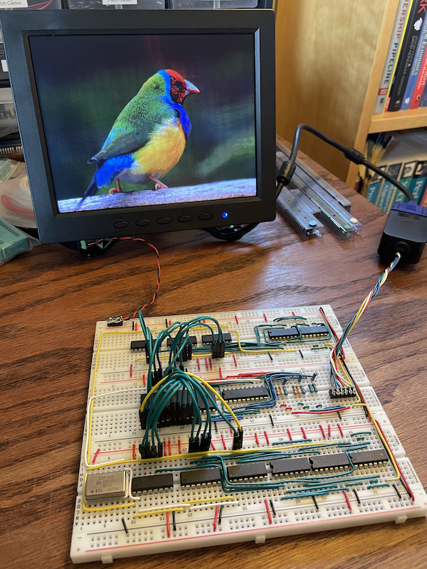
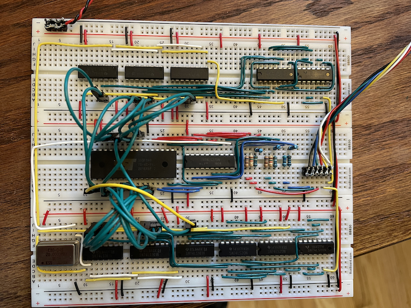
This uses the same general approach as Ben Eater's "world's worst video card", but with a few improvements:
- Reduced chip count (22 => 13) and simplified wiring. The hsync and vsync logic each fit comfortably on a single breadboard, as opposed to two in Ben's origin design.
- 400x300 resolution. A 6502 can't drive this at native resolution, but you could use it to build a serial terminal.
- 8-bit color
- No black vertical lines. These were artifacts of slow EEPROM setup time.
This doesn't strictly adhere to the VGA timing spec. Specifically, the vsync pulse is long and there are a couple glitches on the hsync line after the pulse is over. This works fine on the LCDs I've tested with. I don't know how a CRT would handle it.
You could drop another two chips by running at 200x150 and storing your frame buffer in RAM, but I think this is about as good as you'll get with this approach and resolution.
8x8x4 color uses three bits for red, three for green and two for blue. The values for the resistor ladder don't appear to match Ben's math, but that's because you need to account for the internal 120Ω resistance of the 74LS273.
I wrote my own image converter because I wanted to learn about
dithering algorithms and because I'm too lazy to figure out how to use
Gimp. This script takes an input image, resizes and crops it to
400x300, and subsamples the color to the 8x8x4 color spaced used by
the video card. It outputs a .bin file you can program onto an
EEPROM and a .subsampled.png version that you can look at for
debugging.
docker build -t video-card-converter .
docker run --rm -v $PWD:/6502 -w /6502 video-card-converter ruby convert.rb finch.jpg
minipro -p SST39SF040 -w finch.jpg.binNote that the vsync counters in the upper left are flipped in order to simplify the wire runs.

