energy-monitor


“You can't improve what you don't measure”
This project is a DIY module + a Rust application that aims at measuring grid consumption metrics, display collected values on an OLED display, and send them to an external InfluxDB database for storage.
The module was designed to fit any European-standard distribution boards (same form factor as a circuit breaker) and has 90mm (5-module) width. It does not collect data directly but rather fetches metrics from Lechacal's RPICT module and Enedis Linky electric meter (France national power provider).
I built this project to observe and store my own energy consumption, to eventually improve it. And, well... also because it looked a cool DIY project (it actually was!).
Table of contents
Application
This project includes a Rust application that handles everything, from I/O to display.
Interface
The user interface is composed of several pages that can be cycled using the push button (like a carousel).
Startup screen
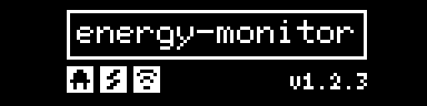
This screen displays the project logo, connection statuses and the current application version. It is shown at application startup and also belongs to the page carousel (last position).
Connection statuses are:
-
 RPICT status, white square means connected.
-
 Linky status, white square means connected.
-
 InfluxDB status, white square means connected.
Instantaneous metrics screen (RPICT)
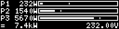
This screen displays instantaneous metrics measured from the RPICT:
- lines apparent power value with a gauge that shows the max seen value since boot
- sum of consumed lines power
- mean of lines RMS voltage
It is the first displayed screen when waking up from sleep.
Cumulated metrics screens (Linky)

This screen displays instantaneous metrics collected from the Linky:
- Linky's counter unique id
- "heures creuses" and "heures pleines" indices, used for billing
Installation
To run the energy-monitor application on a Raspberry Pi Zero W:
- install a fresh Raspberry Pi OS on a SD card
- insert the SD card and open a terminal (desktop or ssh)
- configure the system to enable SPI and UART via the
raspi-confighelper - ensure user
pibelongs to groupspi,gpioanddialoutusing commandusermod -aG spi,gpio,dialout pi - download energy-monitor binary from the Github Release section
- run the application with the
energy-monitorbinary. You can override configuration using YAML config file or environment variables. See Configuration section below for a full list of overridable settings.
$ energy-monitor -h
A tool to measure, display and store electrical consumption metrics.

Usage: energy-monitor [OPTIONS]

Options:
  -c, --config <FILE>  Sets a custom YAML config file
  -h, --help           Print help
  -V, --version        Print version
For advanced users:
- use a systemd service to launch the application at system startup
Configuration
You can configure the application either by providing a YAML config file (see -c --config <FILE> binary arg) or using environment variables:
| YAML path | Environment variable | Description | Default |
|---|---|---|---|
log_level |
APP__LOG_LEVEL |
Application log level | INFO |
hmi.sleep_timeout_secs |
APP__HMI__SLEEP_TIMEOUT_SECS |
Duration in seconds before shutting down display | 30 |
hmi.max_line_power_watts |
APP__HMI__MAX_LINE_POWER_WATTS |
Max expected line power in watts | 6900 |
hmi.button_debounce_ms |
APP__HMI__BUTTON_DEBOUNCE_MS |
Push button debounce duration in milliseconds | 100 |
hmi.button_bcm_pin |
APP__HMI__BUTTON_BCM_PIN |
Push button BCM pin number | 27 |
serial.rpict |
APP__SERIAL__RPICT |
Serial port for RPICT | /dev/ttyAMA0 |
serial.linky |
APP__SERIAL__LINKY |
Serial port for uTeleinfo (Linky) | /dev/ttyUSB0 |
influxdb.host |
APP__INFLUXDB__HOST |
InfluxDB host | localhost |
influxdb.port |
APP__INFLUXDB__PORT |
InfluxDB port | 8086 |
influxdb.database |
APP__INFLUXDB__DATABASE |
InfluxDB database | metrology |
influxdb.prefix |
APP__INFLUXDB__PREFIX |
Application's measures prefix | energy |
Hardware
The module is composed of several parts listed in the Parts section. Electronics parts (push button, OLED display and RPICT) are wired to the Raspberry Pi, see Wiring section. RPICT is tied to the Raspberry Pi module via 29.7mm Brass Standoffs, they are both tied to enclosure's part 1 via clips. The OLED display is tied to enclosure's part 3 the same way.
Parts
The following table presents the partlist needed to build a full module:
| Part | Quantity | Price | Links |
|---|---|---|---|
| Raspberry Pi Zero WH | 1 | 14.60€ | buy |
| 5V 3A Micro USB Power Supply | 1 | 2.30€ | buy |
| Sandisk Micro SD card 16GB Class 10 | 1 | 9.90€ | buy |
| Waveshare 2.23" OLED Display 128×32 Pixels SPI/I2C | 1 | 23.00€ | buy / doc |
| LeChacal RPIZ CT3V1 | 1 | 18.30€ | buy / doc |
| LeChacal EU AC/AC Adaptor | 1 | 15.00€ | buy |
| 3pcs SCT-013-000 Current Transformer | 1 | 11.30€ | buy |
| 3pcs 6x6x4.3MM 4PIN G89 Push Button | 1 | 0.70€ | buy |
| 200pcs M2.5 Brass Standoffs | 1 | 9.90€ | buy |
| (optional) Charles Micro Teleinfo V2.0 | 1 | 22.90€ | buy / doc |
| (optional) 3pcs Micro USB to USB 2.0 adapter | 1 | 5.00€ | buy |
Total price is roughly 130€, not counting shipping.
Wiring
The following tables uses the following Raspberry Pi pinout as reference:

In order to achieve wiring between parts, you may need the following tools/parts:
| Part | Price | Link |
|---|---|---|
| 22AWG Electrical Wire box | 11.80€ | buy |
| 620pcs Dupont Connector kit 1 | 4.00€ | buy |
| 310pcs Dupont Connector kit 1 | 4.00€ | buy |
| SN-28B Pin Crimping Tool | 4.00€ | buy |
RPICT
| RPICT | Raspberry Pi | Physical |
|---|---|---|
| 1 | 3.3 | 1 |
| 6 | GND | 6 |
| 8 | GPIO14 (UART0_TXD) | 8 |
| 10 | GPIO15 (UART0_RXD) | 10 |
OLED display
| OLED | Raspberry Pi | Physical | BCM |
|---|---|---|---|
| VCC | 3.3 | 17 | - |
| GND | GND | 20 | - |
| DIN | MOSI | 19 | 10 |
| CLK | SCLK | 23 | 11 |
| CS | CE0 | 24 | 8 |
| D/C | GPIO5 | 18 | 24 |
| RES | GPIO6 | 22 | 25 |
Push button
| Push Button | Raspberry Pi | Physical | BCM |
|---|---|---|---|
| 1 | GPIO27 | 13 | 27 |
| 4 | GND | 14 | - |
Enclosure


The enclosure contains 3 clippable parts so that it is easier and faster to print on a 3D printer. Assembly only needs a bit of epoxy to hold the push button in place. Don't forget to place the 3D-printed button before glueing the push button! The enclosure was designed using Autodesk Fusion 360.
You can find emonitor-part*.stl STL files in the project's enclosure directory.
I printed mine in 6 hours, using PrusaSlicer as slicer, and with the following parameters:
- 0.20mm SPEED profile
- 20% infill
- support on build plate only
- white 1.75mm PLA filament
Notes:
- don't forget to print the button in your favorite color, see
button.stlSTL file - I also designed an enclosure for utinfo, see
uteleinfo-part*.stlSTL files


