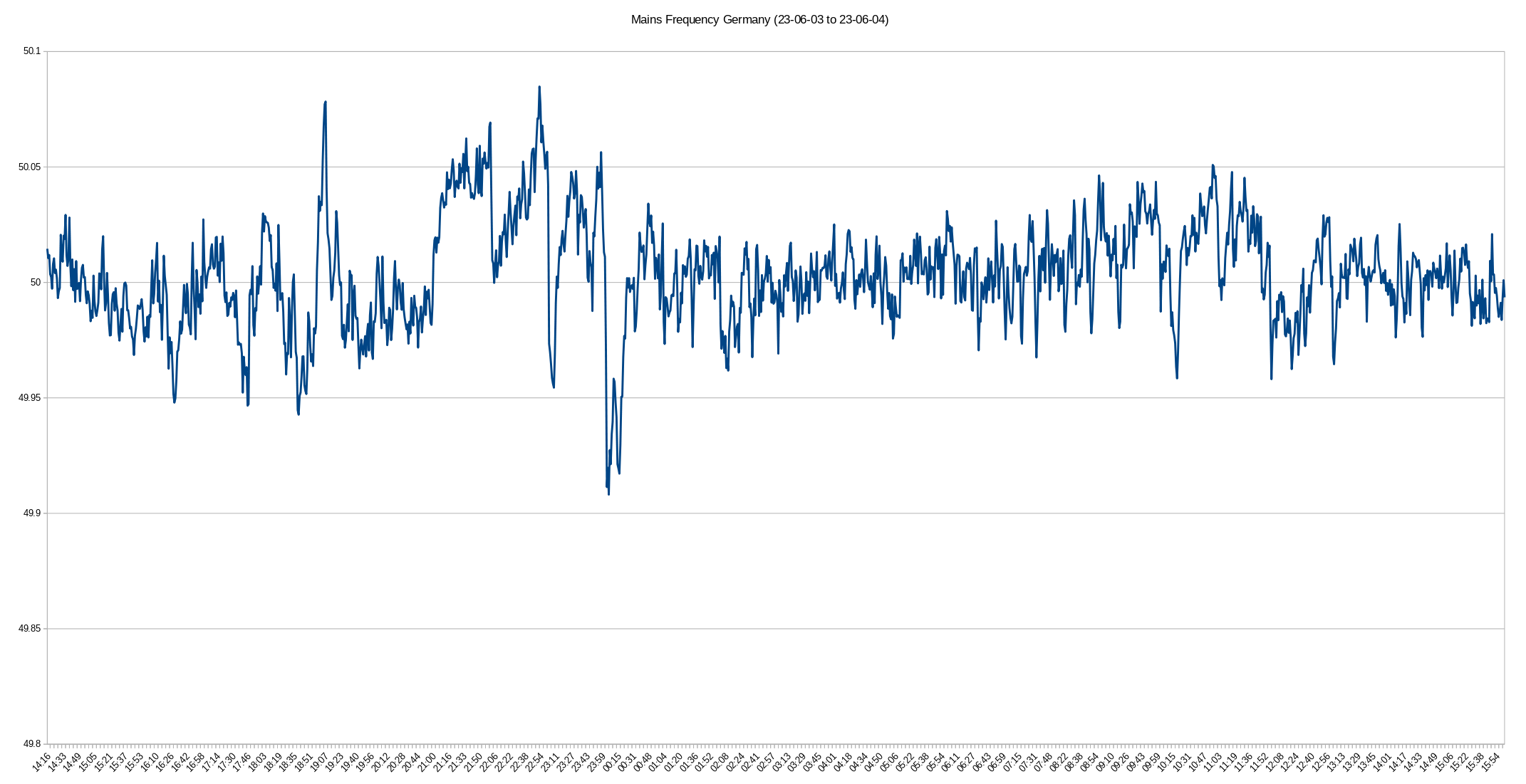
Measures the frequency of mains power.
This device was built as an exercise in digital electronics.
It uses a reciprocal frequency counter approach to measure the frequency of the mains voltage supplying it.
Using two SN74LV8154N 32-bit counters, it counts pulses of the mains signal and the reference clock.
The start and end of the measurement are synchronized to the input signal, using a D-Flip-Flop to open the main gate.
This eliminates the influence of gate time accuracy on the measurement.
The measurement result is then calculated as follows:
The measured value is sent out over serial (J2).
Find a graph explaining the signal flow here.
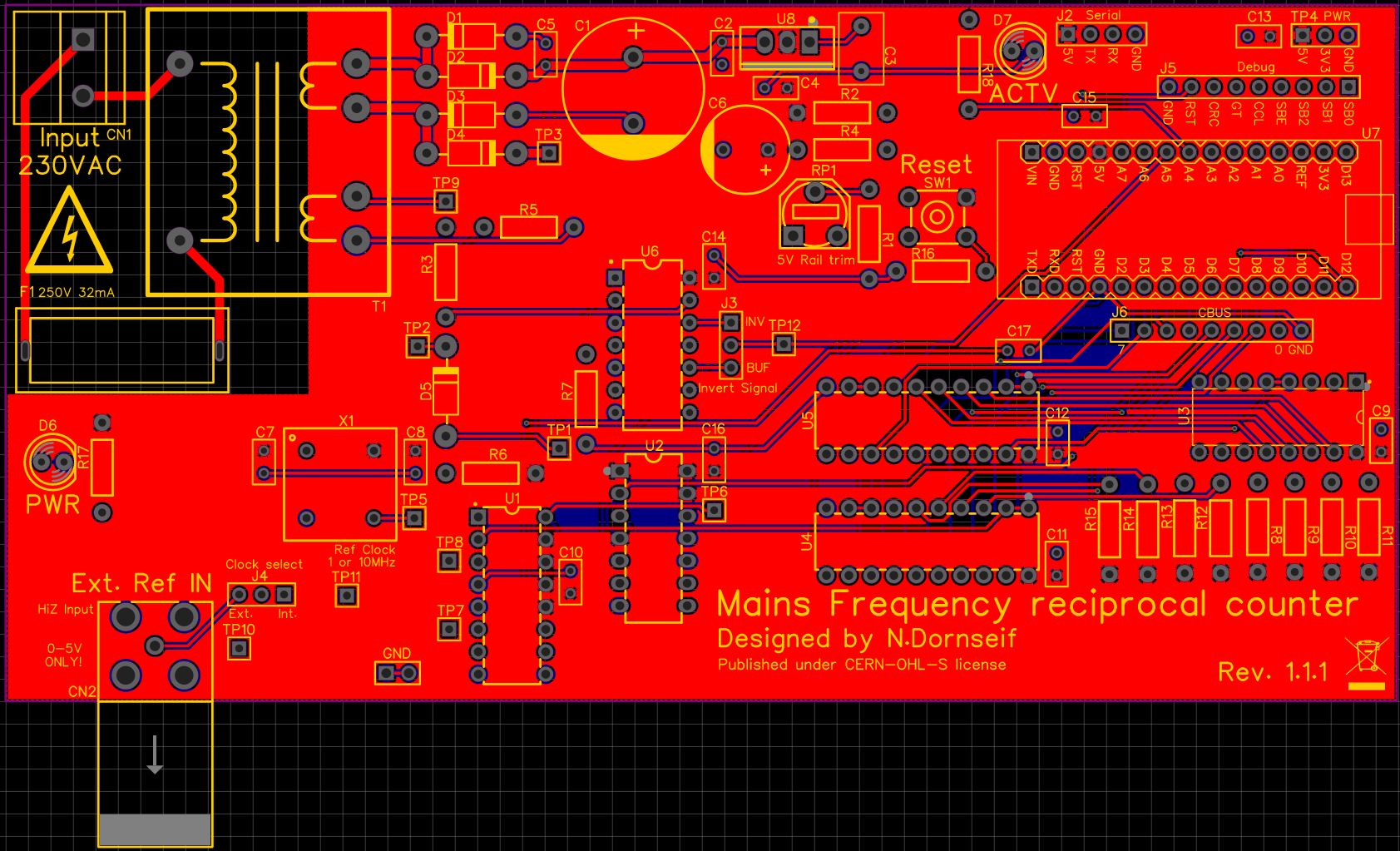
- GND: Ground connection for scope ground clips.
- TP4: DC voltage rails.
- J2: Serial interface. Connected to D0 and D1 of the Arduino. (5V max.)
- J5: Debug pins. (SBUS0, SBUS1, SBUS2, SBUSE, CounterClear, GateTime, CounterRegClock, Reset)
- J6: CBUS. Used to read out the counter values.
- CN1: Mains input. Fuse with a 5x20mm 32mA glass fuse in F1.
- CN2: External reference input. BNC. 0–5V square wave only. HiZ input.
- JMP1 (J3): Selects if the measured signal is inverted. This should not affect the measured value. The recommended setting is INV.
- JMP2 (J4): Selects an external or internal reference clock. Check TP11 for the selected signal.
- TP1: Offset voltage to compensate for the clipping diode drop. (~ 500mV DC)
- TP2: Divided and clipped transformer output voltage. (~ 4Vp half-wave rectified sine)
- TP3: Unregulated rectified and smoothed transformer voltage. (> 17V DC)
- TP4: DC supply rails. (+5V and +3.3V DC)
- TP5: Reference oscillator signal. (1 MHz or 10 MHz 0–5V square wave)
- TP6: Gate-Enable signal from Flip-Flop. High if the main gate is open and the measurement is running.
- TP7: Input to the signal counter.
- TP8: Input to the reference counter.
- TP9: Transformer output voltage to measurement circuit. (> 12V AC)
- TP10: External reference clock input.
- TP11: Reference input to the main gate. Should show the same signal as TP10 or TP5 depending on JMP2 (clock select).
- TP12: Signal input to the main gate. (0-5V square wave with the same frequency as the mains)
- RP1: Use this pot to adjust the voltage of the 5V rail.
Find the firmware for this project in this repository.
You can just upload it using the official Arduino IDE onto the Arduino Nano (U7).
Remove the Arduino from the board when uploading firmware.
Measurement results are in uHz and sent out over serial.
They are sent as ASCII and separated by LF and CR.
Default parameters: 115200 baud, 8 data, 1 stop, no parity
Trying to power the Arduino through its USB header while the device is connected to the mains is not recommended.
Use J2 (serial) for communication while mains is applied.
Published under CERN-OHL-S license.

