NeuroStimDuino
An open source neurostimulator for students, researchers, and hobbyists interested in neuroscience
Important update for 2023
In January 2023 we have launched NeuroStimDuino v2.1, which comes with additional features and improved functionality than its predecessor NeuroStimDuino v1.0.

Here is a list of important upgrades for NeuroStimDuino v2.1 (NSDuino2.1):
-
Choosing between symmetrical and asymmetrical waveform shapes is now done entirely in software. In NeuroStimDuino v1.0, to switch from symmetrical to asymmetrical waveform, you had to change the jumper (J5, J6) as well as call the
SYMMcommand. In NSDuino2.1, its handled entirely by software and the jumpers have been removed. In the default asymmetrical output mode, the anodic phase's amplitude is half of cathodic phase's amplitude and the duration of anodic phase is double that of the cathodic phase (to ensure charge balance). This ratio can be changed by modifying the firmware. -
NSDuino2.1's I2C address is now stored on EEPROM. So, whenever you assign a new I2C address to NSDuino2.1 using the
ADDRcommand, it will get stored permanently and will be recalled at power-on reset. This is especially helpful when communicating with multiple NeuroStimDuinos. In NeuroStimDuino v1.0, the address would reset to the default value (0x1A) everytime the board was turned on and you would have to painstakingly re-assign the new addresses each time. With NSDuino2.1 the new address only needs to be set once and it will store it on-board its EEPROM. -
Many of NeuroStimDuino v1.0 users (who are acutally scientists!!) have asked whether it is possible to ramp up and down the stimulation intensity? Ramping is used in neurostimulation research to avoid painful sensations allow smoother transitions between movements when applying electrical stimulation. With NSDuino2.1, we have also expanded our software (Arduino) library and now provide the option to Ramp Up and Down the stimulation intentsity. When you enable ramping by using the command
RAMP 1, the stimulation intensity will gradually increase from 0 to the desired level over a 1 second interval. At the end of stimulation, the stimulation intensity will gradually decrease to zero over a 1 second interval. There are some caveats to using ramping:- In the scientific literature, ramping is usually done by increasing/decreasing the current amplitude. While this is doable, by changing the counts of our on-board digital potentiometer, it would require multiple SPI calls between the MCU and potentiometer which will introduce delays. Instead, we are performing ramping by gradually increasing the stimulation pulse-width. This is handled entirely by the MCU and hence it is more accurate. Additionally, it has the same effect as changing the stimulation current, so it won't affect the outcomes of your experiments. Refer to the below gif to understand how ramping essentially works:

- Currently, ramping only works for finite stimulation intervals. This means the
Stim Indefinitelyflag of theSTIMcommand must be set toFALSE. An example code snippet is as follows:
RAMP 1 // Turn ON ramping on channels 1 & 2 STIM 1 5 0 // Stimulate on channel 1 for 5 sec, stim indefinitely flag = 0 RAMP 0 // Turn OFF ramping on channels 1 & 2- Ramping can also be deployed in NeuroStimDuino v1.0. This would require a firmware update. We will post an upgraded firmware for NeuroStimDuino v1.0 on our repository in a few weeks time. Feel free to reach out to us for any queries regarding ramping
-
Additional minor modifications:
- We removed the bi-color(red/green) LEDs to indicate when channels 1 and 2 are stimulating, with regular monocolor LEDs. These still function in the same way

- We changed the onboard cable connectors for Channels 1 & 2 with new ones that are compatible with our stimulation cables and you no longer need to remove the cable shroud or sheath cover. This will hopefully help reduce the hassle during setup and the touchproof connectors will offer additional safety during use.

Getting Started Tutorial for NeuroStimDuino v2.1
Important: For instructions on getting started with NeuroStimDuino v1.0, please click here
- To get started, first and foremost familiarize yourself with NeuroStimDuino pinout and board layout below:


- If you have ordered the NeuroStimDuino board (without the accessory pack), then you will have received the following components.

-
You also need to order a pair of hydrogel electrodes (from any retail vendor) if you plan to stimulate a fake muscle (such as a Zucchini) or for your research.
-
Finally, before you begin, please remember to review the safety guidelines listed at the end of this tutorial and follow the recommendations mentioned therein.
Hardware Setup
- The battery holder included requires two 18650 Li-ion batteries (not included) to be connected in series. The battery holder allows the batteries to be oriented in series or parallel connection. Unfortunately, the battery holders we shipped only have Chinese labels to indicate the series or parallel oritentation. Make sure you connect the batteries in series (as shown below) and not in parallel. Alternately, you can power NeuroStimDuino using your own battery source between 6-20V. We do not recommend powering NeuroStimDuino using an AC-DC adapter. However, if you must use an adapter, then you need an adapter with atleast 2 Amps output rating

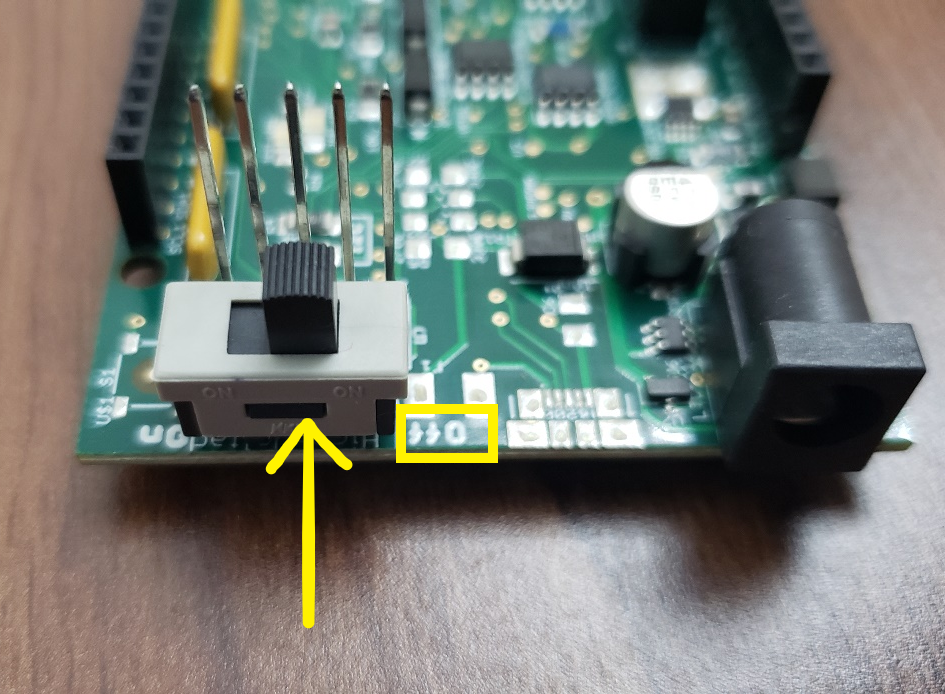
- The High-Voltage Power Switch S3 turns ON/OFF the +/-72V DC-DC converter (NMT0572SC). When using NeuroStimDuino for the first time we recommend starting with the switch in OFF position. Afterwards, once you are ready to stimulate then flip the switch ON. That way even if you accidentally turn ON the stimulation, it will not have any effect because the high-voltage source will be OFF. Plus it will also help extend battery life.
- To control NeuroStimDuino using an Arduino Due or Mega, stack NeuroStimDuino on top of the Arduino board by aligning the hearder pins, as shown below.

- Once the hardware setup is complete, the amber or yellow Emergency-OFF LED will remain continuously ON. Also TEST_LED1 and TEST_LED2 will start blinking at a rate of 5 blinks per sec.

Software Setup
-
Next, you will need to download the latest version of our Arduino library. Read the full update here and remember to install the [SerialCommands library] (https://github.com/ppedro74/Arduino-SerialCommands) from Pedro Pereira. Next, upload the example code NeuroStimDuino_SerialControl.ino onto the Arduino.
-
To write instructions to control NeuroStimDuino, you will use the Serial terminal that is in-built Arduino IDE (Tools > Serial Monitor). Once you open the Serial Monitor, set the baudrate to 115200 bps and add "CR+LF" at the end of each command. When you power either the Arduino or NeuroStimDuino board via the DC plug, you will see test LEDs 1 & 2 flashing on the NeuroStimDuino board. These LEDs are flashing with the default stimulation frequency of 10Hz. Now you can enter some example commands into the Serial Monitor, one command at a time and then press enter.
-
After uploading the example code NeuroStimDuino_SerialControl.ino and making the connections as above, when you first open the Serial terminal you will see the following welcome message. This mean that a successful connection between Arduino and NeuroStimDuino has been established. It will also give a readout of the current stimulation parameters for each channel.

- You can type in some example commands into Serial Monitor and change the settings for the stimulator (type one statement at a time). Also, the commands are case-sensitive, so type it in all caps.
FREQ 1 20        // This will set Channel 1's frequency at 20Hz. You will see the TEST LED1 blink at this new frequency
FREQ 2 50        // This will set Channel 2's frequency at 50Hz. You will see the TEST LED1 blink at this new frequency
AMPL 1 15        // Set Channel 1 intensity 15mA
DURN 1 500       // Set Channel 1 pulse duration at 500 uSec
ENAB 1 1         // This will enable Channel 1 of the stimulation. By default, both channels are enabled at reset
STIM 1 20 0      // This command will turn on stimulation on Channel 1 for 20 seconds. Ensure that the High Voltage Power Switch is ON.
                 // You will see a Red-Green LED (labelled Ch. 1) blink  very briefly (for 500us), every time the stimulation is generated (i.e, 20  times/sec)
Moving forward
-
This completes this introductory tutorial. From here on, if you would like to connect cables and electrodes and actuatlly stimulate a fake Zucchini muscle, then follow the setup instructions shown in our April Update published on CrowdSupply.
-
If you want connect multiple NeuroStimDuinos together and control them using a single Arduino, then look up the steps and instructions posted earlier. Note that with NeuroStimDuino_v2.1, when you change the board's I2C using the
ADDRcommand, the new address is saved on-baord its EEPROM and will be recalled even after reset. It is the User's responsiblity to reset the default I2C to0x1Aif they wish to. -
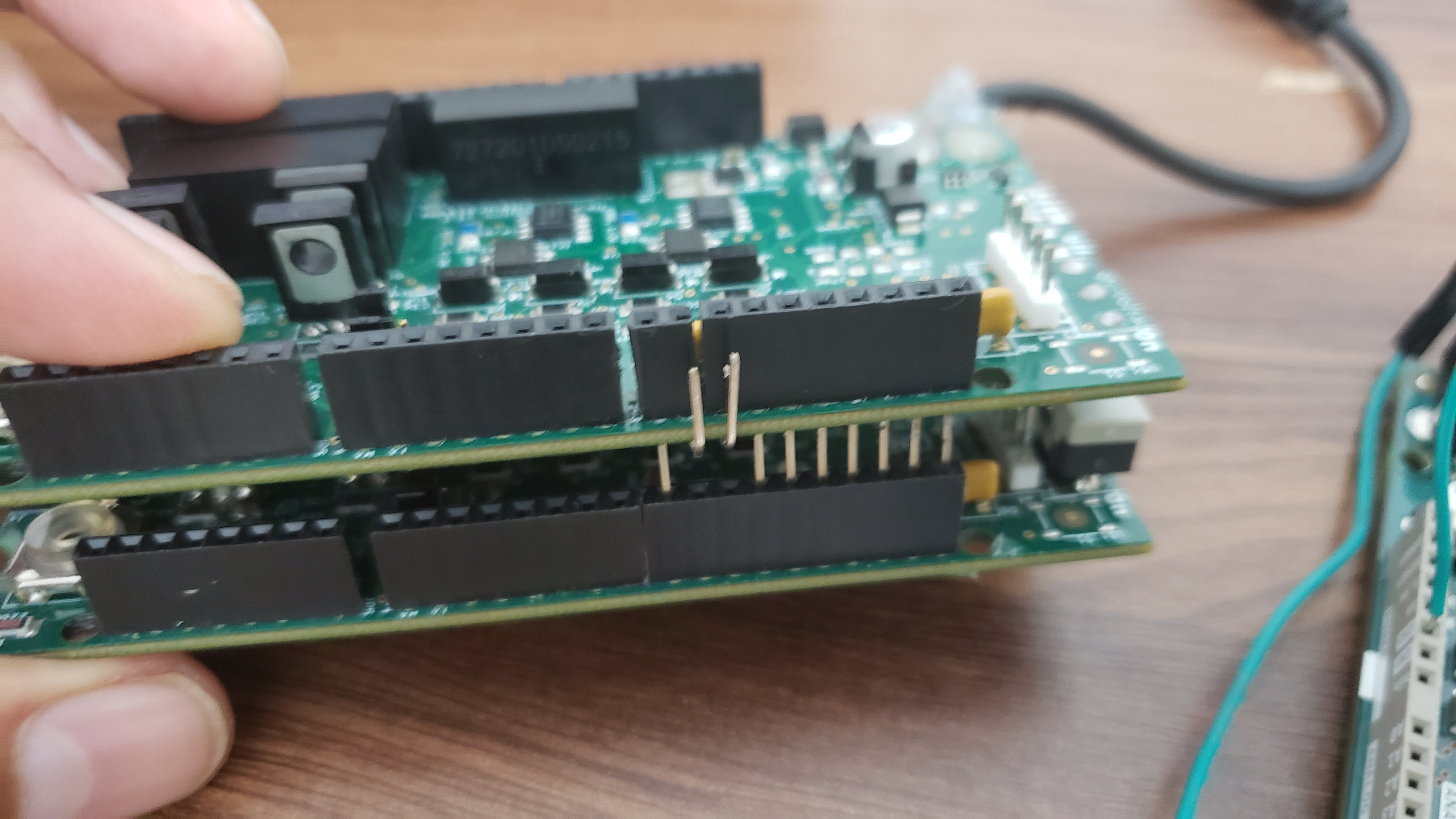
One important change required in hardware when stacking 2 or more NeuroStimDuinos is to disconnect pins 5 & 6 on JP3. Another way to identify these pins is that they normally connect with PWM pins 9 and 10 on Arduino Due or Mega. The reason for this is that these pins can also be used to drive TEST_LED1 and TEST_LED2 of NeuroStimDuino. Therefore, if you connect them together on 2 NeuroStimDuinos, the LEDs will not function properly and can be confusing. Hence, to avoid any cross-talk, its best to fold these pins out of the way as shown below.
- We hope you enjoy tinkering with NeuroStimDuino and use it for all your neuroscience experiments. If you face any issue with the device or are stuck anytime, feel free to write to us on contactus@neuralaxy.com or submit an issue here.
Important safety guidelines:
- NeuroStimDuino is not an FDA approved product for clinical use and it is intended for RESEARCH PURPOSES ONLY.
- NeuroStimDuino is not intended for human use or animal use, without receiving prior approval from a local ethics committee such as Institutional Review Boards and Institutional Animal Care and Use Committees
- Under no circumstances, should the stimulation electrodes be placed across the chest or close to the heart
- NeuroStimDuino requires an external DC input voltage from 6-20V to operate. We strongly recommend to use an external battery for this and avoid the use of an AC adapter or anything that's plugged into the AC mains --->