The goals / steps of this project are the following:
- Compute the camera calibration matrix and distortion coefficients given a set of chessboard images.
- Apply a distortion correction to raw images.
- Use color transforms, gradients, etc., to create a thresholded binary image.
- Apply a perspective transform to rectify binary image ("birds-eye view").
- Detect lane pixels and fit to find the lane boundary.
- Determine the curvature of the lane and vehicle position with respect to center.
- Warp the detected lane boundaries back onto the original image.
- Output visual display of the lane boundaries and numerical estimation of lane curvature and vehicle position.
Rubric Points
Here I will consider the rubric points individually and describe how I addressed each point in my implementation.
1. Provide a Writeup / README that includes all the rubric points and how you addressed each one. You can submit your writeup as markdown or pdf. Here is a template writeup for this project you can use as a guide and a starting point.
You're reading it!
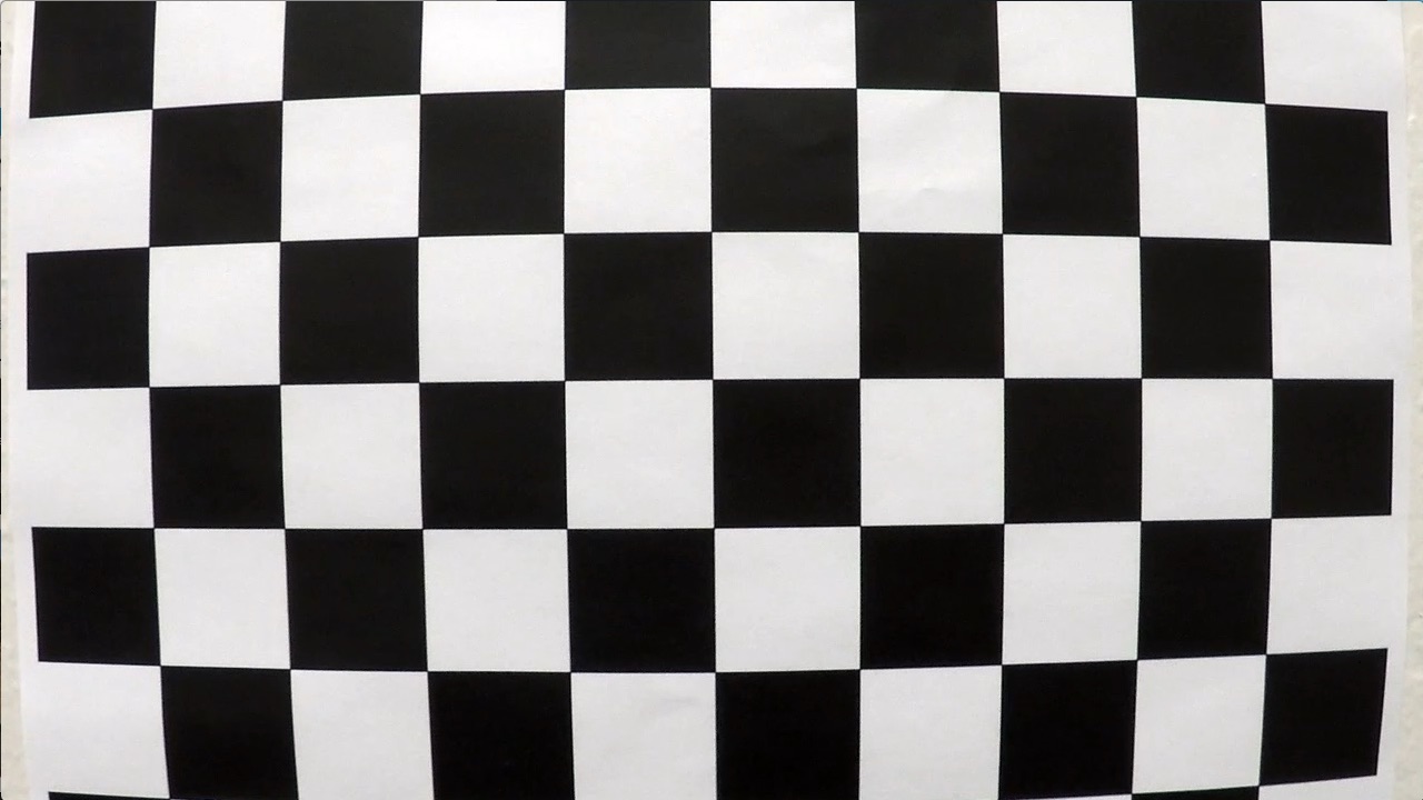
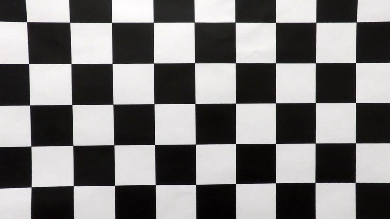
1. Briefly state how you computed the camera matrix and distortion coefficients. Provide an example of a distortion corrected calibration image.
The code for this step is contained in the calibrate.py file.
I started by preparing the both the object points and image points needed to use the cv2.calibrateCamera() function. The object points are added to an array only if all of the corners are detected in the image. Some images did not have all the corners. From here, the image points are appended to another array. Once all images are ran through, both object points and image points arrays are given as inputs to cv2.calibrateCamera() for a distortion correction. I could then use the distortion correction for cv2.undistort() to get an undistorted image output from an image and distortion correction input. The examples below can be found in the "./camera_cal/" subdirectory. Here is an example of a before and after:
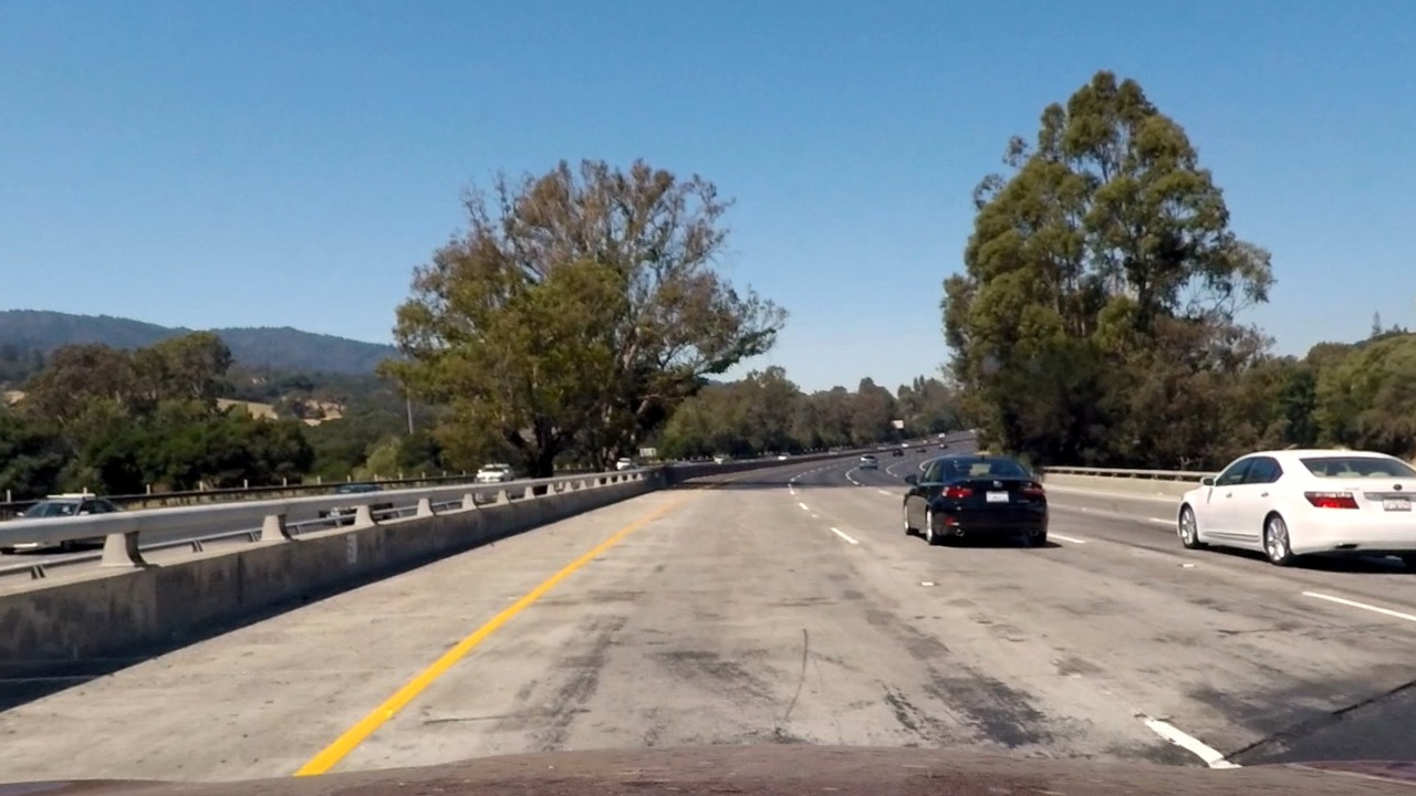
To demonstrate this step, I will describe how I apply the distortion correction to one of the test images showing the before and after below:
Before (Distorted):

As you can see, both cars on the left and right in the image look closer after undistorting. The process involves taking the calibration data saved as "/camera_cal/calibration_pickle.p" to get the distortion coefficients. Once we have that data, we can use cv2.undistort() with the distortion coefficient and source image to get an undistorted image. This was added to the pipeline so every image in the video would be undistorted.
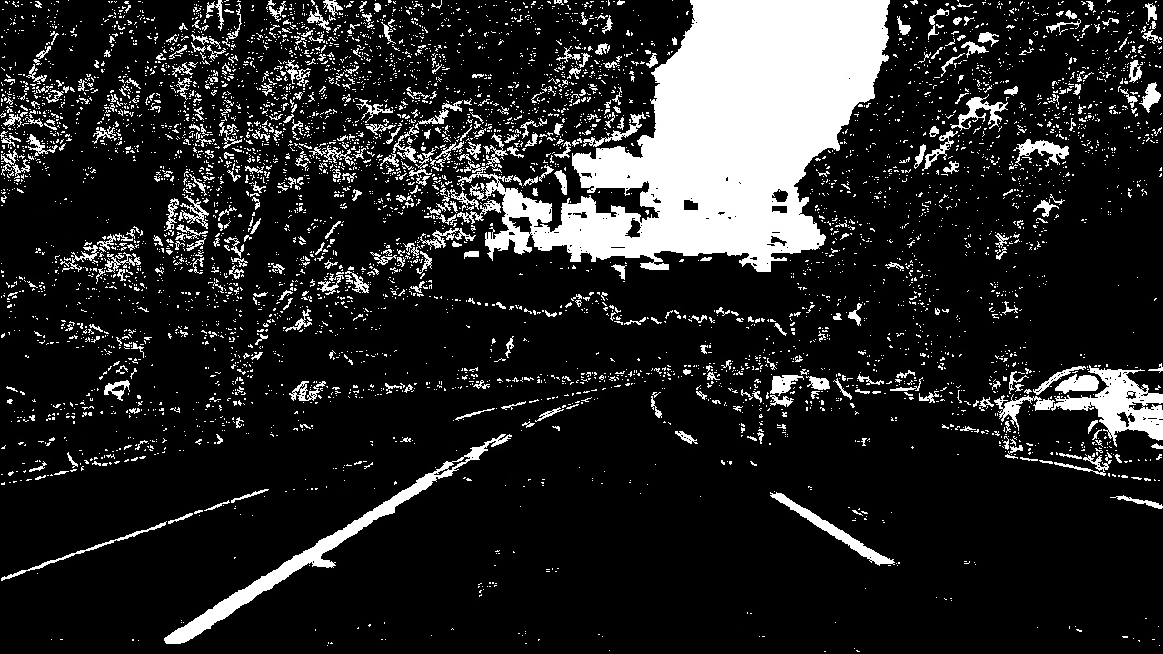
2. Describe how (and identify where in your code) you used color transforms, gradients or other methods to create a thresholded binary image. Provide an example of a binary image result.
I used a combination of color, gradiet, blurring, and regioning to get a thresholded binary image. The better the preprocessing of the image before the perspective transform phase, the better the end result.
- Pipeline: Grayscale -> Sobel Threshold -> Color Threshold -> Region Mask -> Gaussian Blur -> Perspective Transform
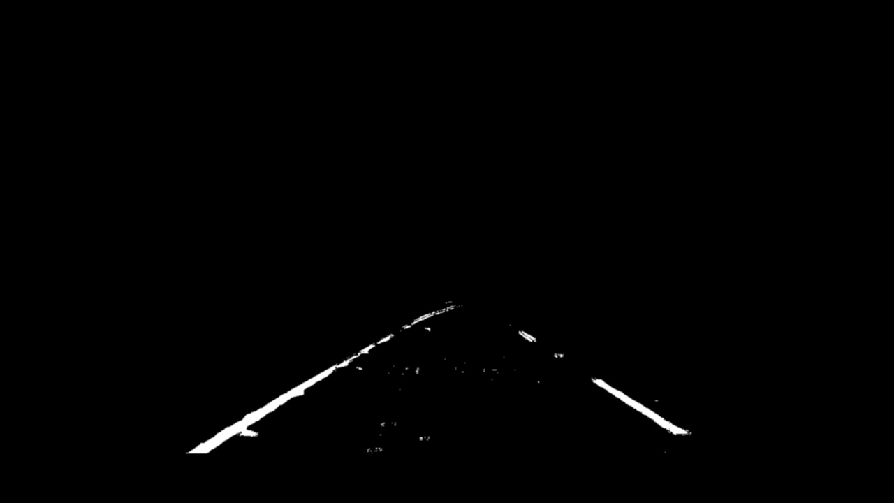
I used some of the techniques from the first project to aid in preprocessing; I was able to reuse my region and gaussian blur functions. I first started by grayscaling the image to feed it into the Sobel Thresholding function for both the x orientation and y orientation. This produced an image with edges, similar to the Canny Edge Detector from project one. From here, I ran this new edged image through Color Thresholding to get the lane markers (white and yellow color). An example of the produced image so far is below:
Now, I ran this image into a Region mask to filter out everything not within a trapezoid centered with the lanes; again, similar to project one. This image was then run through a Gaussian Blur filter to remove some noise. An example of the final preprocessed image is shown below:
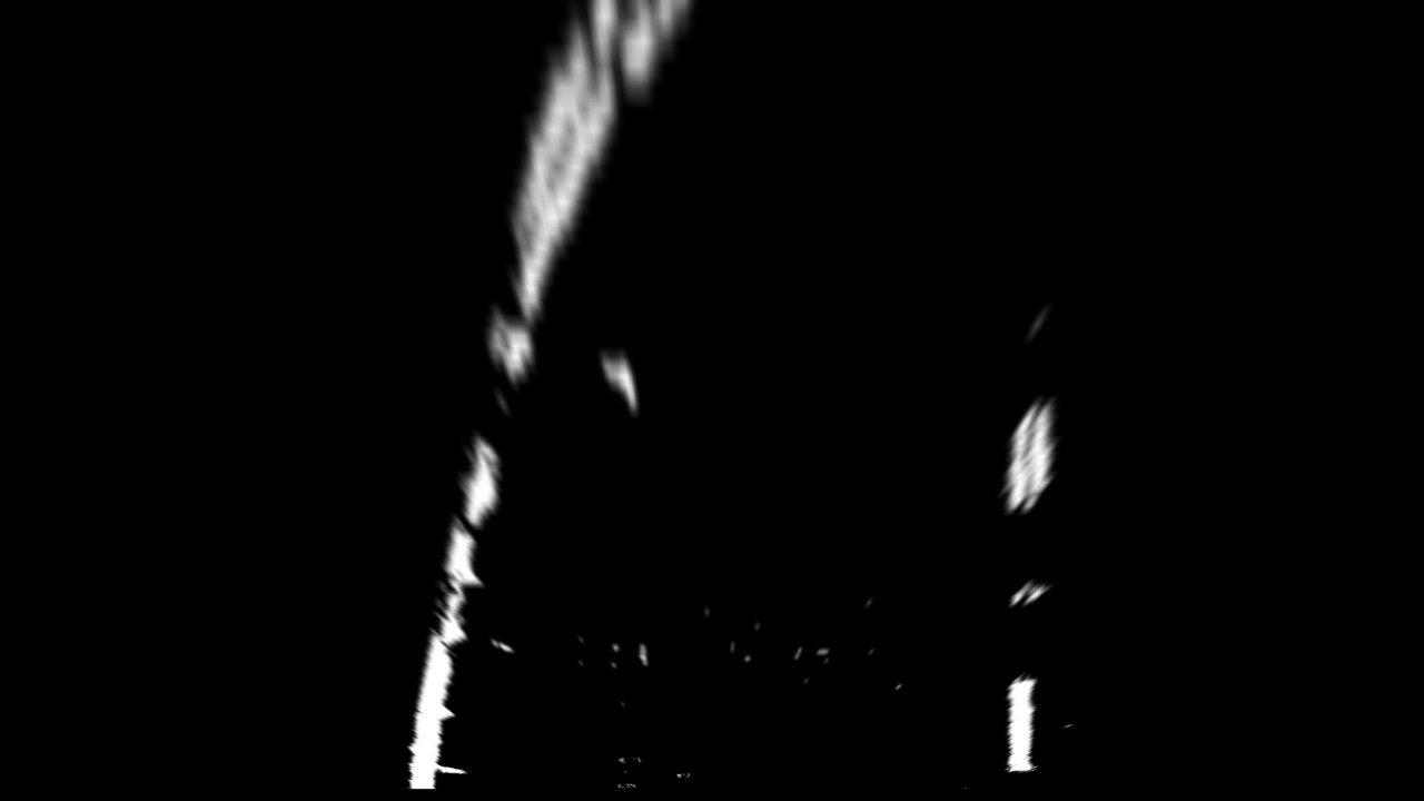
3. Describe how (and identify where in your code) you performed a perspective transform and provide an example of a transformed image.
The code for my perspective transform in inside the perspective_transform() function in the file video_processor.py in lines 108 to 130. The function takes the undistorted image and and the binary thresholded image as inputs and then returns the transformed image, the transform and inverse transform. Below is the code showing how the source and destination were coded for the transform:
-
src = np.float32([ [image.shape[1] * (.5 - middle_width/2), image.shape[0]*height_percent], [image.shape[1] * (.5 + middle_width/2), image.shape[0]*height_percent], [image.shape[1] * (.5 + bottom_width/2), image.shape[0]*bottom_trim], [image.shape[1] * (.5 - bottom_width/2), image.shape[0]*bottom_trim]])
-
dst = np.float32([ [offset, 0], [image_size[0]-offset, 0], [image_size[0]- offset, image_size[1]], [offset, image_size[1]]])
I verified that the transform was working by ouputting the warped counterpart; an example can be seen below:
4. Describe how (and identify where in your code) you identified lane-line pixels and fit their positions with a polynomial?
Code for identifying the lane lines can be found in tracker.py. It uses convolution to find the max in vertical slices to find the most probably location for the left and right lanes. The tracker takes in the warped image and uses previously found lane points to search for the new lane points. It then returns the new found lane points and saves them for the next frame.
Back in video_processor.py in the process_image() function, the left and right lanes are fitted as a polynomial starting at line 220. The calculated polynomials are then drawn onto the image with the draw_resulting_image() function starting on line 132. This function uses cv2 to draw the lines.
5. Describe how (and identify where in your code) you calculated the radius of curvature of the lane and the position of the vehicle with respect to center.
The radius of curvature and the center offset were calculated in the metrics() function in the video_processor.py file starting on line 151. First, I set the values mapping pixels to meters. Having these constants, we can use the equation shown in lecture to find the polynomial coefficients in meters to then computer the radius of curvature. The center offset is calculated by finding the difference of the center of the car and the center between the left and right lanes. The camera is assumed to be centered on the vehicle.
6. Provide an example image of your result plotted back down onto the road such that the lane area is identified clearly.
Finally, the lane lines are drawn onto the image in the draw_resulting_image() function starting on line 132 of the file video_processor.py. Below is an example of the result plotted back onto the image:
1. Provide a link to your final video output. Your pipeline should perform reasonably well on the entire project video (wobbly lines are ok but no catastrophic failures that would cause the car to drive off the road!).
Here's a link to my video result
1. Briefly discuss any problems / issues you faced in your implementation of this project. Where will your pipeline likely fail? What could you do to make it more robust?
As can be seen in the video, my implementation works reasonably well. It starts to strafe off a little when the road changes color like in the beginning, but is able to adjust back quickly. Experimenting some more with the preprocessing (sobel and color thresholding specifcally) could help out a bit more.
I also used a convolution method to find the lanes in the perspected transformed image. To supplement this, I could also use the Sliding Window algorithm discussed in lectures to run concurrent and then compare the two results. This would make the tracking more robust.
Another improvement that can be made includes adding logic to detect when the lanes are lost (too many frames with bad lanes for example). This would fix the few instances when my implementation veers a bit off from the lane markers as can be seen in the video.
