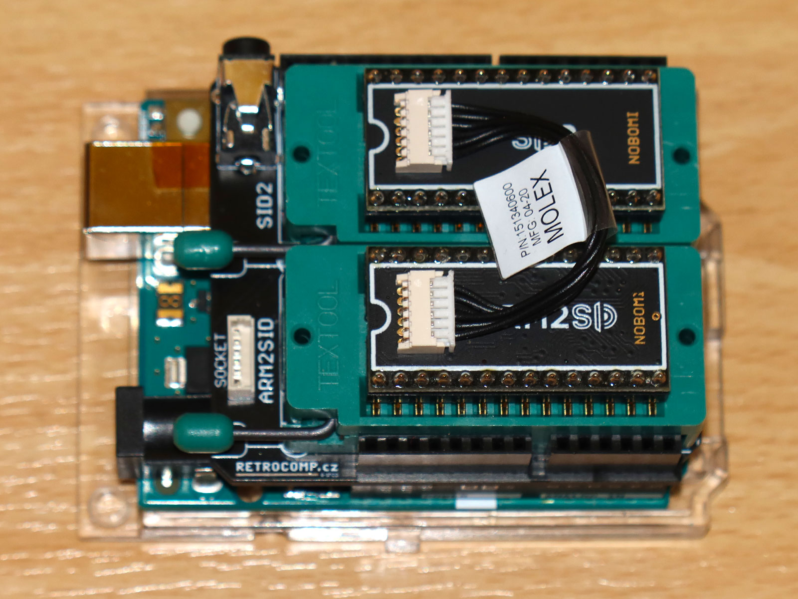
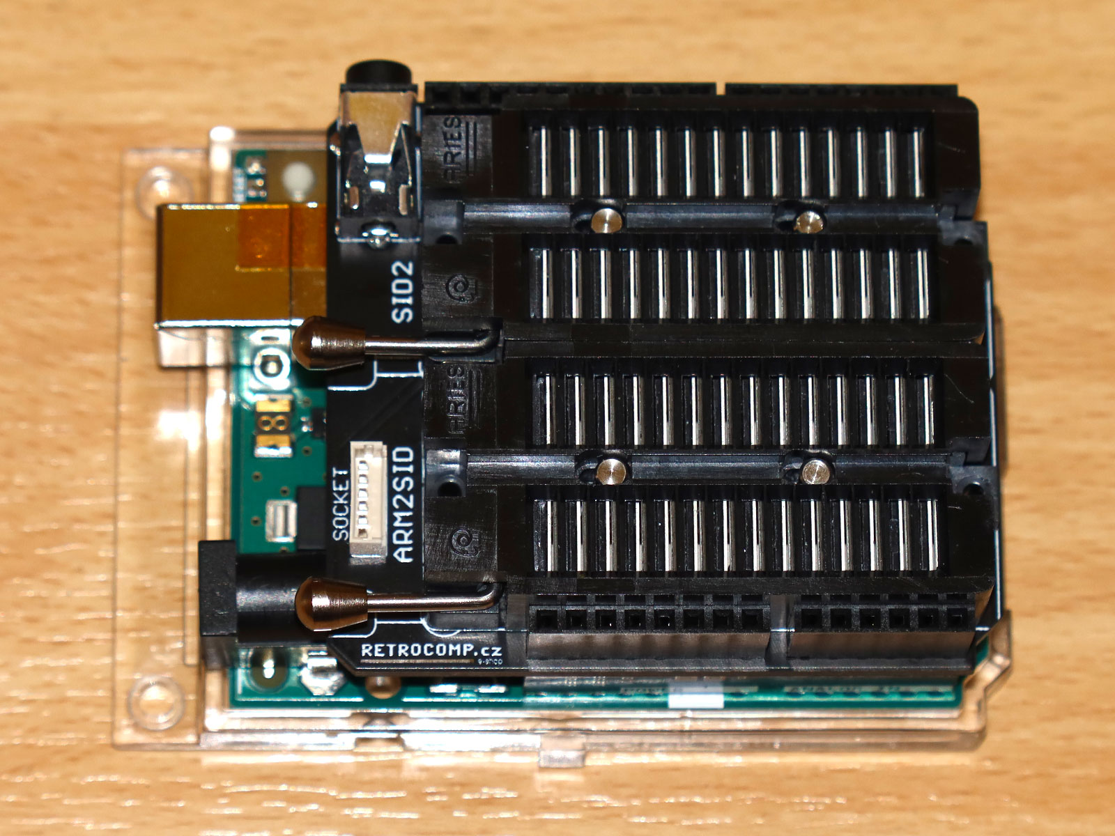
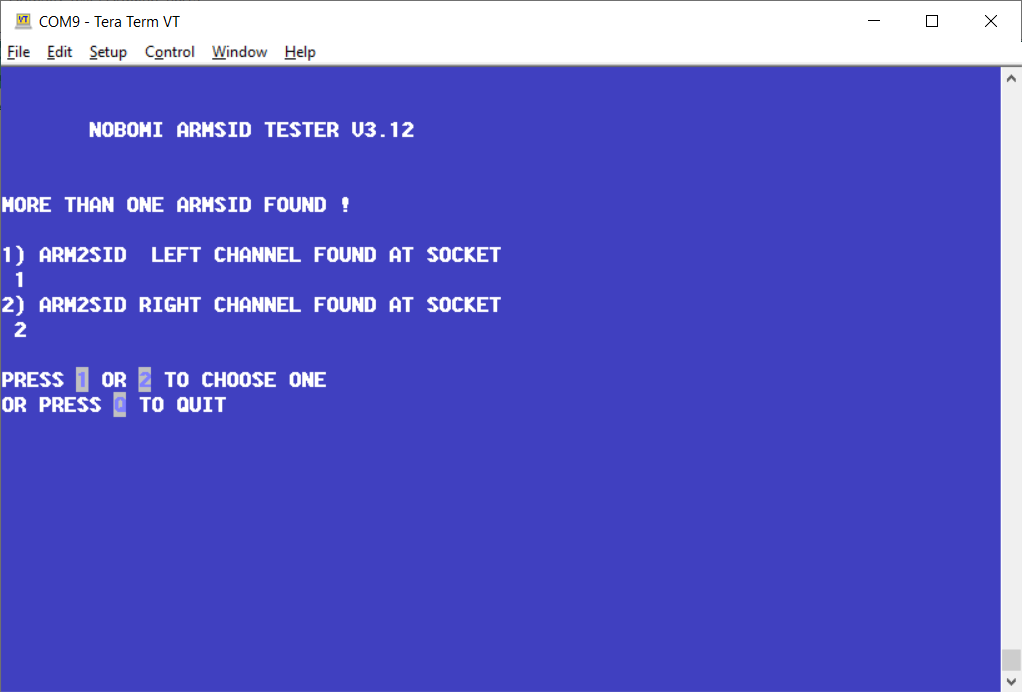
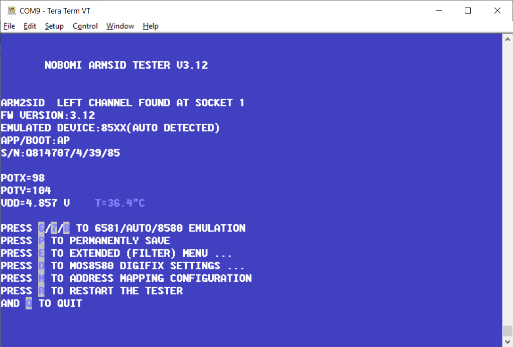
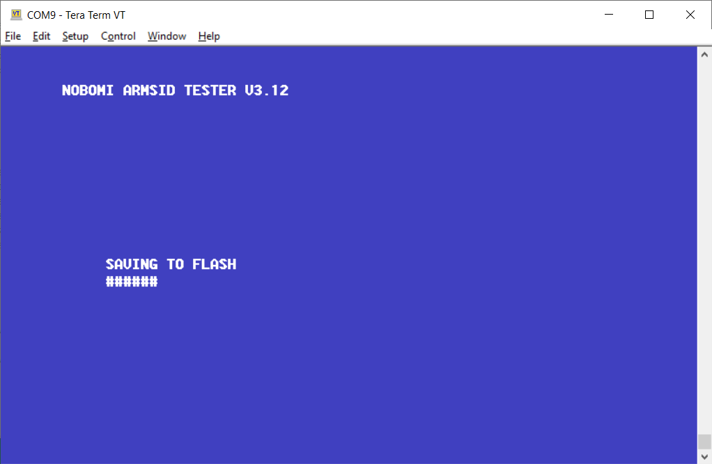
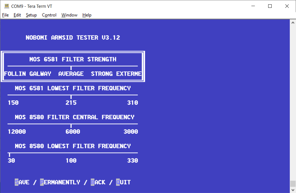
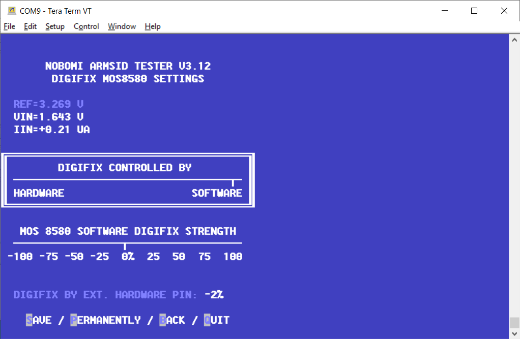
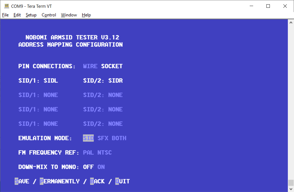
Simple Arduino shield with a sketch for ARMSID and ARM2SID configuration using Tera Term or similar ANSI terminal program. It allows:
- configure ARMSID or ARM2SID parameters (SID type, address mappings, filters, digifix, ...)
- update ARMSID or ARM2SID firmware
- play some SIDs to a 3.5 mm stereo audio jack (more than 60 ohms headphones or line input connection only)
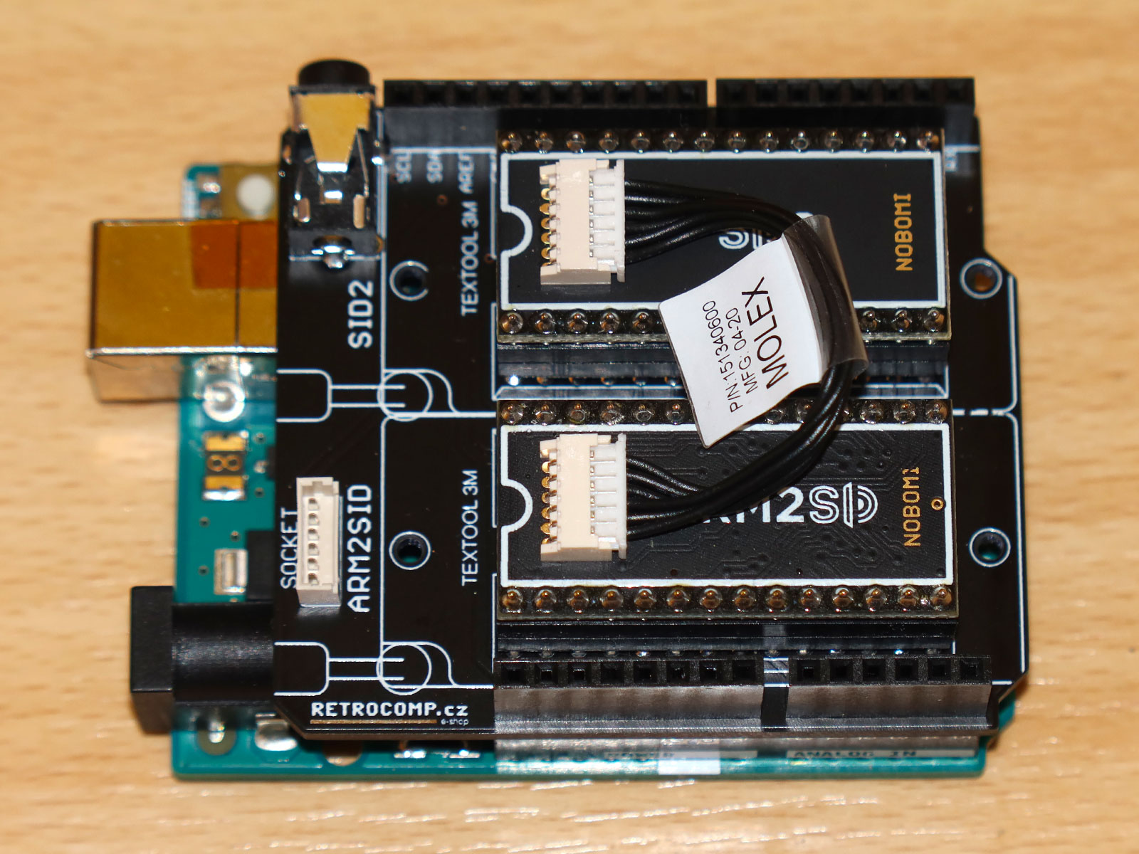
Main DIL28 socket for ARMSID or ARM2SID to be configured.
DIL28 socket for the 2nd ARMSID or SID2 (ARM2SID). When using SID2, please use 6-pin PicoBlade connector with 5 cm wire to connect SID2 to ARM2SID.
Stereo audio output for headphones or amplifier line input.
| Pin | Description |
|---|---|
| Tip (the inner outer contact) | Output: Audio left (>60 ohms or line level) |
| Second row (the inner middle contact) | Output: Audio right (>60 ohms or line level) |
| Ring / Sleeve | Ground (GND) |
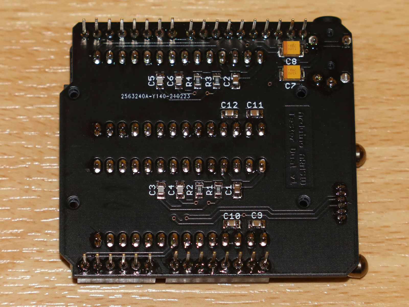
Note: When connecting headphones, the impedance should be at least 60 ohm. Note2: Shorten the connector legs near the board edge to not exceed the hole before soldering. Solder without creating solder (tin) bump, clean and cover with Kapton tape, as it could conflict with Arduino USB connector otherwise.
6-pin MOLEX PicoBlade connector for ARM2SID 2nd SID connection. Use 10 cm 6-pin PicoBlade connectors wire to ARM2SID instead of populating SID2 socket.
| Pin | Description |
|---|---|
| 1 | GND |
| 2 | GND |
| 3 | Output: R/W (R/W signal for the 2nd socket) |
| 4 | Output: CS2 (CS signal for the 2nd socket) |
| 5 | GND |
| 6 | Input: Audio right |
Arduino pin headers used to connect to Arduino UNO. Only models with ATmega328P should be used, such as Arduino UNO Rev3 or Arduino UNO Rev3 SMD.
| Component type | Reference | Description | Quantity | Possible sources | Notes |
|---|---|---|---|---|---|
| PCB | Arduino ARMSID configurator shield PCB | 1 | Order PCB or parts kit at Retrocomp.cz e-shop or order from a PCB manufacturer of your choice using provided Gerber or Eagle files | ||
| Resistor | R1, R2, R3, R4 | 110 kohm, SMD 0805 | 4 | Digikey RMCF0805FT110KCT-ND | Needed only if you want to test POT inputs |
| Capacitor | C1, C2 | 100 nF, SMD 0805 | 2 | Digikey 490-11955-1-ND | |
| Capacitor | C3, C4, C5, C6 | 2.2 nF, SMD 0805 | 4 | Digikey 490-6448-1-ND | Needed only if you want to test POT inputs |
| Capacitor | C7, C8 | 10 uF, SMD 3528 | 2 | Digikey 478-4975-1-ND | Needed only if you want to use stereo audio output |
| Capacitor | C9, C10, C11, C12 | 15 nF, SMD 0805 | 4 | Digikey 490-5718-1-ND | Needed only if you plan to use real SIDs (no sufficient power provided for real SIDs on current design) |
| DIP/DIL Socket | ARM2SID, SID2 | 28 pin DIL socket (preferably ZIF) | 2 | Digikey 3M2802-ND or A302-ND | The second (SID2) DIL socket si needed only for the ARM2SID's 2nd SID configuration and can be substitued by 10 cm 6-pin PicoBlade wire to the SOCKET connector. |
| Connector | AUDIO1 | Audio connector JACK 3.5 mm - type FC68125 | 1 | Farnell 2309468 | Needed only if you want to use stereo audio output |
| Connector | SOCKET | Molex PicoBlade 6-pin vertical header | 1 | Digikey WM1735-ND | Needed only if you want connect ARM2SID to board without SID2 |
| Connector | B1 | Arduino stackable header kit | 1 | Digikey 1568-1413-ND | |
| Arduino | B1 | Arduino UNO Rev3 | 1 | Digikey 1050-1041-ND or 1050-1024-ND |
- Version 1.0
- 3.5 mm audio JACK touches the Arduino USB connector. Solder without tin bump and isolate with Kapton tape!
- No power supply for real SIDs. The 5V provided is not sufficient for MOS 6581 nor 8580.
DARRELL A. WESTBURY created nice guide for configuring and updating ARMSID/ARM2SID using Arduino shield GET IT HERE. He also shared his experience with setup and using ARM2SID in MB6582. Thank you!
