Arduino code for Nitramite Nuclear Radiation Detector Android application. This repository exists so that app users can get code, open issues and make contributions.
To get started see firmware versions part or look table of contents for more.
Making this hardware requires a little bit of knowledge with Arduino's, soldering, wiring and maybe little bit of Arduino programming depending on which Geiger counter hardware you are using and how much it required you to customise this code.
- How did I do it?
- Related links
- Firmware versions
- Hardware schematic
- Oled screen support (optional)
- Fritzing parts (for schematic drawing)
This is my version how did I do it just for reference.
- You need any hardware capable to be connected to Arduino. I connected my Aliexpress kit to Arduino digital pin three.
Arduino code is doing CPM measurement and transformation to uSv/h. Arduino sends readings to Android app every 10
seconds.
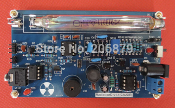
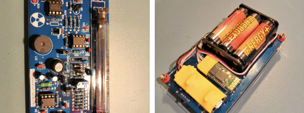
Kit I bought looked like this. You can use any kit which has Arduino cababilities. Usually told at description of item. - You don't need to modify reading output from Arduino code but if you do, remember to have it in form like:
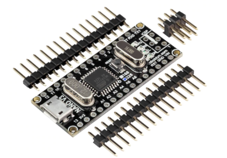
cpm=924;uSv/h=7.5029App will look for splitter char;->cpm=anduSv/h=extract values and show them. Arduino code also sends all ticks as t; don't modify this or remove it. - I used this kind of Arduino Nano:
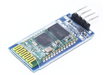
I used HC-06 bluetooth module to send data from Arduino. It looks like this:
- Use hardware schematic section drawing to solder wires according to instruction.
-
- Serial.prints are actual TX which arduino bluetooth module will output for Android application. Don't change that.
- So what ever you do, don't change output format. You can output any values you want with specified titles as tests.
- I am using Arduino Nano and HC-06 module. You can use what ever you like.
- I tested my cheap kit with americium-241 which was found from old fire detector.
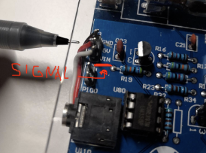
- Note: this cheap kit signal pin is labeled as VIN which is misleading. See image below which shows where
connection
point between Arduino and Geiger counter is in this specific kit.
If you have questions about this app or Arduino side, open issue or https://nitramite.com/contact.html.
- Heres final product:


Android Application
Youtube promo video
To use only basic Geiger counter, Bluetooth module and Arduino combo, just download basic first version code relase 1.0.0.
To support oled screen or any other future hardware, download current main branch code.
Repository has updated Schematic made with Fritzing. Some more information could be found from here.

Here is some information about Oled screen support.
SSD1306 Oled
- SDA -> A4 (i2c)
- SCL -> A5 (i2c)
- GND -> Ground
- VDD -> 5v (Screen pin labeled as VCC or VDD)
- Adafruit BusIO
- Adafruit-GFX-Library
- Adafruit_SSD1306
Good tutorial:
https://randomnerdtutorials.com/guide-for-oled-display-with-arduino/

Custom parts which may not be found from Fritzing by default