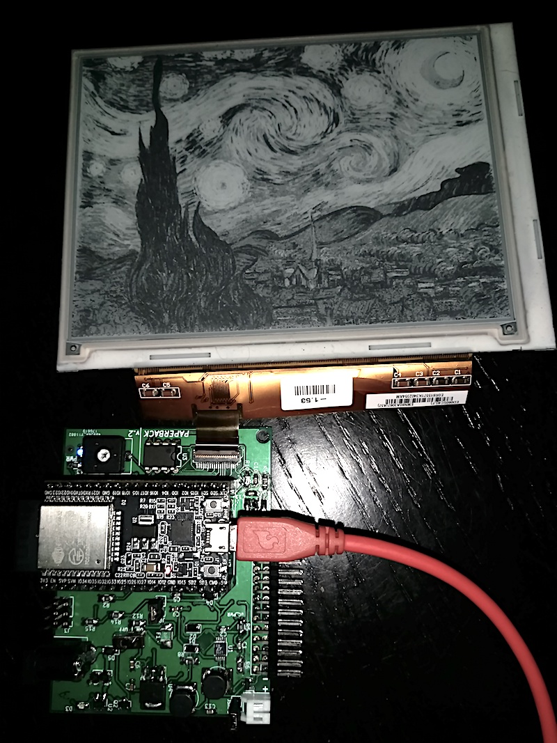
PaperBack EPaper Display
PaperBack is a modular, internet connected OR VGA EPaper Display. It consists of a breakout board for a 39 pin ePaper display and an ESP32 in one mode. In the other, remove the ESP32 and attach a VGA Conversion board and use regular VGA input to drive the display!
PaperBack is an entry in the 2017 Hackaday Prize, you can see a more complete (and verbose!) writeup here.
Hardware Overview
Currently, PaperBack works both driven by an ESP32 Development Board, or directly via VGA with the attached second PCB.
Hardware Overview:
- Espressif ESP32 Dev Board
- ED060SC4 // LB060S01 // LB060S04 6" ePaper Display
- 800x600 Resolution
- 16 Color (Greyscale) Support / 4-Bit Grey
Software/Firmware Overview
Remember, choose one at a time! You can use the ESP32 breakout board with the ESP32 dev board, or remove the dev board and attach the VGA converter.
VGA Driven
Unplug any ESP32 from the socket and attach both boards, then attach power (see below). When the board detects a signal it will start to refresh.
All firmware is in the /firmware_VGA/FPGA and /firmware_VGA/Microcontroller directories.
The user switches change color depth (read: shades of gray. 2 color is black & white.) and refresh speed: Switch 3 (Furthest from Microcontroller) Switch 2 Switch 1 (Closest to Microcontroller)
- On On On - 16 color, ~10 seconds between frames
- On On Off - 16 color, ~5 seconds between frames
- On Off On - 4 color, ~10 seconds between frames
- On Off Off - 4 color, ~5 seconds between frames
- Off On On - 4 color, ~1 frame per second
- Off On Off - 2 color, ~10 seconds between frames
- Off Off On - 2 color, ~5 seconds between frames
- Off Off Off - 2 color, ~1 frame per second
ESP32 Dev Board Driven
Remove the second PCB if attached, then add the ESP32. There are easy ways to add power (there are pins exposed too, but these are easiest). Unless using Lithium and the DC adapter, only use one at a time!
- The board supports a single cell lithium ion battery with JST connector, and can charge it through the DC adapter hookup. Polarity is marker.
- The board can take a 2.1mm jack DC adapter, center positive. Aim for between 4.8 and 7 volts (don't create too much heat with something more).
- Disconnect all other supplies if you do this, but you can power it over USB from the ESP32. Connect the jumper labeled 'JP2' for this option.
Demos:
- The Python utility
convert.pyin/software/image_converterautomatically converts images which are compatible with Paperback's basic image demo. The image demo is in /firmware_ESP32/Paperback_Greyscale_Static_Image.
Licensing and Other
- My main site: DQYDJ
- Where available, all of the code is licensed as MIT.
- Where available, all of the hardware is licensed as MIT.
- If needed, other licenses will be quoted for individual parts.
- I would, of course, love a link if you use any assets - but feel free to use everything as you wish.
