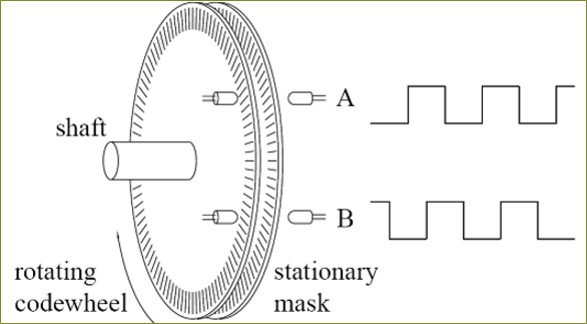
An optical encoder "channel" is composed of a pair of light (optical signal) emitter and receiver.
The stationary codewheel has alternating opaque and transparent sections (stripes) on it. When optical signals are able to be received (i.e. between the emitter and receiver is a transparent section), the channel outputs a HIGH (1) digital signal. Otherwise the channel outputs a LOW (0) one.
When our motor shaft starts rotating, the optical channels start to output HIGH and LOW signals alternatively, hence generates a square wave signal, shown in the image above.
We detect triggers (both falling and rising edges) to determine occurance of a state transition.

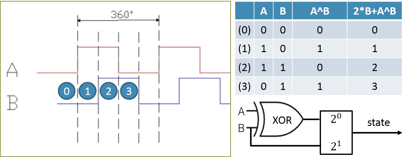
A "Quadrature" encoder means that there are 2 channels (A, B) * 2 states (1, 0) = 4 possible combinations (states).
Here I represent the encoder state with an XOR logic analogy, shown in the table in above image.

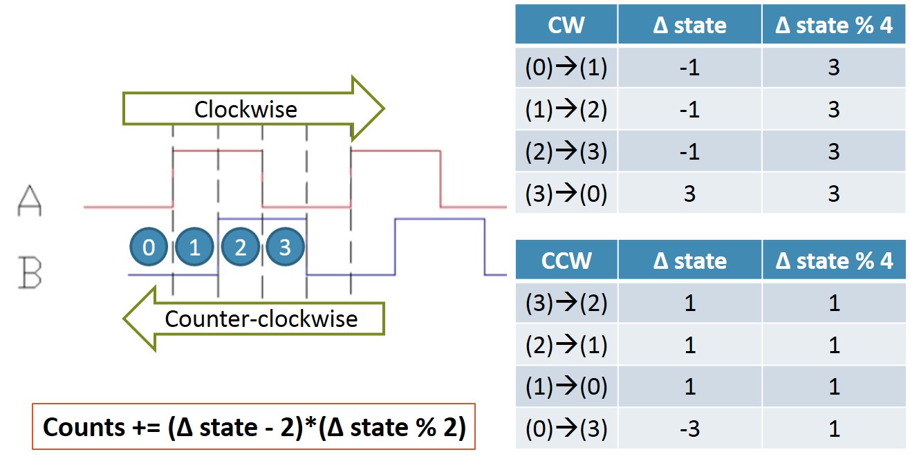
What differs a quadrature encoder from a regular one (or with only one channel) is that with the extra channel, rotation direction of motor shaft can now be determined.
We compare the current state with the previous one to determine the rotation direction. Details are described in the image above.
BCM2835 edge triggering usage is described in the code.
We use threading for synchronously reading from different channels and transmitting counts.
Corresponding pins:
define FXA RPI_GPIO_P1_11
define FXB RPI_GPIO_P1_15
define FYA RPI_GPIO_P1_16
define FYB RPI_GPIO_P1_18
define RXA RPI_GPIO_P1_10
define RXB RPI_GPIO_P1_08
define RYA RPI_GPIO_P1_19
define RYB RPI_GPIO_P1_21