This repository contains an example of bare-metal code for PWM as described in TB3270 - Getting Started with PWM Using CCP on PIC18 document from Microchip.
The PIC18F47Q10 features four 10-bit PWM generators. This example describes how to configure the CCP1 peripheral in conjunction with TMR2 to produce a low speed PWM signal.
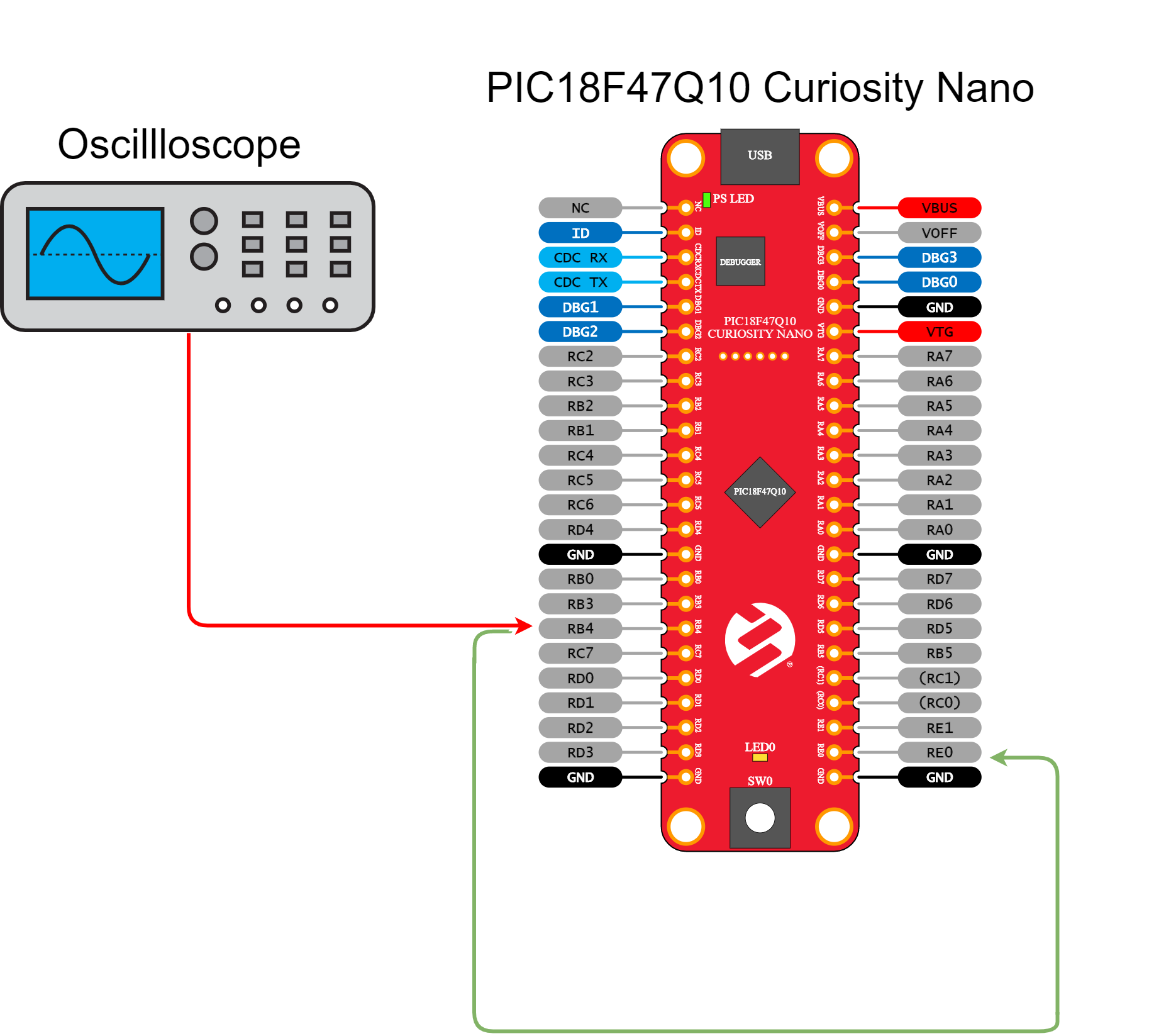
Two GPIO pins are used. RE2 as an input to read the on-board button for controlling the demo and RB4 as a PWM output.
- TB3270 - Getting Started with PWM Using CCP on PIC18
- PIC18-Q10 Product Family Page
- PIC18F47Q10 Data Sheet
- TB3261 - PIC1000: Getting Started with Writing C-Code for PIC16 and PIC18
- PIC18F47Q10 Code Examples on GitHub
- MPLAB® X IDE 5.30 or newer (microchip.com/mplab/mplab-x-ide)
- MPLAB® XC8 2.10 or newer (microchip.com/mplab/compilers)
- Microchip PIC18F-Q Series Device Support 1.3.89 or newer (packs.download.microchip.com/)
- PIC18F47Q10 Curiosity Nano (DM182029)
- Oscilloscope or logic analyzer for visualization - optional
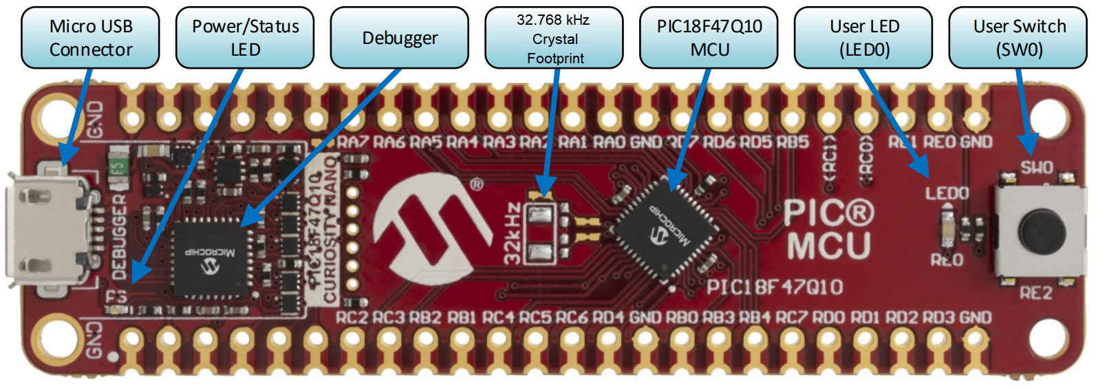
The PIC18F47Q10 Curiosity Nano Development Board is used as the test platform.
The following configuration is done for this example:
- RB4 pin - Configured as digital PWM output (CCP1)
- RE2 pin - Configured as digital input with pull-up for button SW0
- RE0 (LED0) pin kept as input - Optionally used for LED visualization
To run this example, there are two options, choose one of the following:
- hook the oscilloscope probe on RB4
- run a wire between RB4 and RE0

Then run the code, RB4 will generate a PWM signal with a frequency of 1Hz. To demonstrate the run-time update of the PWM parameters, SW0 push-button is used.
- A short press produces a change of duty-cycle in steps of 25%
- A long press produces a change of frequency from 1Hz to 4Hz in steps of 1Hz
This project showcases how to configure basic PWM functionalities, such like duty cycle and frequency on the PIC18F47Q10 microcontroller. The example shows both initialization of the CCP1 and TMR2 for PWM and update of parameters at run-time.

