![]()
because Laz00rs!
An cheap and DIY open source lasertag system, build with an ESP-32. Lasertag works with infrared. The tagger is build with a infrared LED and a infrared receiver, through which the players can hit each other. This basic functionality is given by the tagger and can be tested with two or more taggers standalone. For more complex games the esp32 is paired via bluetooth with a android app (work in progress). With the android app and a internet connection it will be possible to track statistics during a game and create more complex games e.g. with GPS location data.
This project currently consists of three parts:
- ESP-32 Firmware (https://github.com/open-laser-tag/tagger-firmware)
- Android App (https://github.com/open-laser-tag/android-app)
- node.js Server (https://github.com/open-laser-tag/server)
Videos about Open Laser Tag:
- Lightning Talk from Chaos Communication Congress 2019, English, multiple other languages available, 2nd last talk: https://media.ccc.de/v/36c3-10524-lightning_talks_day_2#t=6194
- Lightning Talk from Chaos Commuinication Camp 2019, German, English dub available, 2nd last talk : https://media.ccc.de/v/Camp2019-10380-lightning_talks#t=10043
clone repository with submodules
git clone git@github.com:open-laser-tag/tagger.git --recurse-submodules
There are a lot of options for writing code for the esp32 and for flashing it e.g. Arduino IDE, VScode with Arduino extention, PlattformIO. All possibilities to develop with the esp32 are listed and described here.
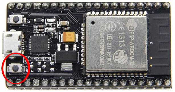
When uploading to esp32, don't forget to press IO0 on it when it tries to connect to the esp32.
When you want to keep track of which firmware is flashed on your tagger, you can add update_git_hash.sh as git hook to your local git repository. Just add a file named post-commit to .git/hooks/ and add the line ./update_git_hash.sh or run this script manually before flashing, when you are not using the makefile.
Prepare your IDE like described and then open
tagger.ino
chose ESP32 DevModule as Board
set partition scheme to Minimal SPIFFS (Large
Your arduino.json could look like this
{
    "port": "/dev/ttyUSB0",
    "board": "esp32:esp32:esp32",
    "configuration": "PSRAM=disabled,PartitionScheme=min_spiffs,CPUFreq=240,FlashMode=qio,FlashFreq=80,FlashSize=4M,UploadSpeed=921600,DebugLevel=debug",
    "sketch": "tagger.ino",
    "output": "./build"
}
All necessery informations are already provided in platformio.ini. When your esp32 is connected via USB you can simply press upload.
When you have installed PlatformIO on your computer, you can just use the provided Makefile in this repository and run
make upload to download all dependencies, build the code, and upload it to your ESP-32 in one step.
- install esptool.py with their instructions
- Download both .bin files from newest release.
- Flash ESP with
esptool.py --chip esp32 --port /dev/ttyUSB0 write_flash 0x10000 tagger_firmware.ino.bin 0x8000 tagger_firmware.ino.partitions.bin(+ press Button IO0)
One tagger is made of: 1x ESP32, 1x IR LED TSUS 5202, 1x IR receiver TSOP31238, 1x power bank, 1x micro usb cable, some RGB LEDS WS2812 or APA102, 1x lense, 1x 20 Ohm Resistor, 1x push button. The price for all this parts is about 10€.
The pins for the wiring can be set or looked up in tagger.h. Or look at the schematics below.


When the tagger is connected via BLE, it is reporting the changes of its trigger and the incoming IR. With a connection the tagger doesn't send any infrared by its own and it doesn't control its LEDs. In BLE there can be different services, characteristics and properties on one device, which are building the BLE API. The tagger is running the following characteristics:
| UUID | Name | Properties | Description |
|---|---|---|---|
| 08dbb28a-ce2c-467a-9f12-4f15d574a220 | tagger service | all characteristics below | This service contains all tagger Characteristics. |
| 756ad6a4-2007-4dc4-9173-72dc7d6b2627 | trigger | notify | Get a notify about the trigger trigger status every time it changes. 1 for pressed, 0 for not pressed |
| a95980fb-4f18-4b2e-a258-81bf77575117 | IR receive | notify | Get a notify about the message when a message is incoming via infrared. |
| 8b91a0d2-5f7f-49cb-8939-4455d3d24b81 | IR send | write | Send a message to the tagger, to send it via infrared. |
| 60e44cef-5a43-407b-8d1a-bce02377dcfd | latency | notify | Get a notify about the time between the pressed trigger and the sent infrared. This is just for testing purpose. |
| 563c139f-3eda-4c88-9fc3-be987038fa6a | version | read | Read the tagger firmware version. |
| 7a4821c2-80f0-4eba-8070-d659d31e43de | led | write | Tell the tagger the color codes for the RGB LEDs: 0xNNRRGGBBNNRRGGBB... NN (uint8) is the position of the LED. RR (uint8) is red. GG (uint8) is green. BB (uint8) is blue. |
| eebc6352-2559-40f1-bda8-2715e7c07fbd | OTA | write | Write any data to this characteristic to turn on OTA mode. |
The main communication for a laser tag game is infrared. One IR LED TSUS 5202 is used to send IR. One IR receiver TSOP31238 is used to detect infrared. Multiple receivers could be probably easily implemented. Both directions are using the RMT peripheral. The infrared protocol can be chosen with IR_PROTOCOL, but it has to be the same on all devices. Currently it is NEC.
When the OTA signal is given via BLE, the tagger reboots in OTA mode. In OTA mode the tagger connects to a wifi given by OTA_WIFI_SSID and OTA_WIWI_PASSWORD. When no connetion is established in TIME_WAITING_FOR_CONNECTION_IN_MS (current: 10s), the tagger reboots again in normal mode. When the connection is established, the taggers firmware can be flashed via the local ip address through wifi.
More informations: https://docs.espressif.com/projects/esp-idf/en/latest/api-reference/system/ota.html
When wifi connection is established but no new firmware is coming in, the tagger will stay in this status. When you want to get back to normal mode, just reboot the tagger (cut off power).
When the tagger is not connected via BLE, it does some things by its own to test some basic functionalities.
| LED | name | description |
|---|---|---|
| 0 | tagger status | blinking red - choose your team with the trigger, red - tagger on and no BLE, blue - BLE established |
| 1 | player status | green - active, turns red for PLAYER_DOWNTIME_IN_MS (3s) when infrared message by another team is incoming |
| 2 | team | shows one of 7 team colors, the team differs the infrared message |
| 3 | trigger | blinking white when pressing trigger |
The makros of esp_log.h are used to send serial debug messages. When you open a serial monitor and connect the esp32 via USB you should see them. The build flag DCORE_DEBUG_LEVEL must be set for this. When you are compiling with plattformio, this is already done in plattformio.ini. In the arduino ide you have to set Tools->Core Debug Level. For the arduino extention in vscode the example above already gives the right flag.
When you got a JTAG adapter e.g. jlink you can also do inline debugging with the unified debugger of plattformio.
This project is licensed under the terms of the GPL-3.0.