This code implements a Finite Element Method for discretization and solution of two-dimensional truss problems. The governing equations are discretized within the FEM and the resulting linear system of equations is solved with a LU Factorization found in PETSc suite.
To use, it is necessary
- python 3;
- matplotlib;
- numpy;
- petsc.
There are five *.txt files for inputting the nodes, elements connectivity, boundary conditions and properties.
The elements connectivity is written as:
first_node_1 second_node_1 # first_element
first_node_2 second_node_2 # second_element
...
The nodes coordinates (in meters) are listed as:
x_position_1 y_position_1 # first_node
x_position_2 y_position_2 # second_node
...
The Dirichlet boundary conditions are given by "node_number direction value", in which direction is 1 for "x" and 2 for "y" and the value should be in meters:
node_number direction value # 1 for x-direction and 2 for y-direction
...
The Neumann boundary conditions are also given by "node_number direction value", in which direction is 1 for "x" and 2 for "y" and the value should be in N:
node_number direction value # 1 for x-direction and 2 for y-direction
...
The input properties are the Young's modulus and the section area, the former in Pa and the latter in m²:
value_1 # Young's modulus, in Pa
value_2 # Section area, in m2
To run this code, first edit the "CMakeLists.txt" file with the location of PETsc installation. Set the problem with the input files and call the "truss.sh" script.
The results are exported to *.txt files in the export folder and plotted to *.png files in the plot folder.
The displacement field obtained by the solution of the linear system of equations is exported to the trussSolution.txt file as:
u_displacement_1 # Displacement (in meters) in x-direction for node 1
v_displacement_1 # Displacement (in meters) in y-direction for node 1
u_displacement_2 # Displacement (in meters) in x-direction for node 2
v_displacement_2 # Displacement (in meters) in y-direction for node 2
...
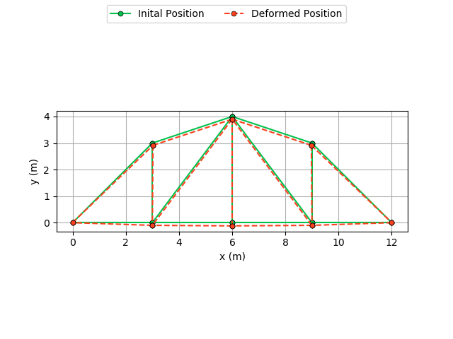
The nodes position is plotted in initial configuration and deformed configuration. This results are found in the trussDeformed.png file.
The reaction forces obtained by the solution of the truss problem is exported to the trussReactions.txt file as:
reaction_in_x_1 # Reaction force (in N) in x-direction for node 1
reaction_in_y_1 # Reaction force (in N) in y-direction for node 1
reaction_in_x_2 # Reaction force (in N) in x-direction for node 2
reaction_in_y_2 # Reaction force (in N) in y-direction for node 2
...
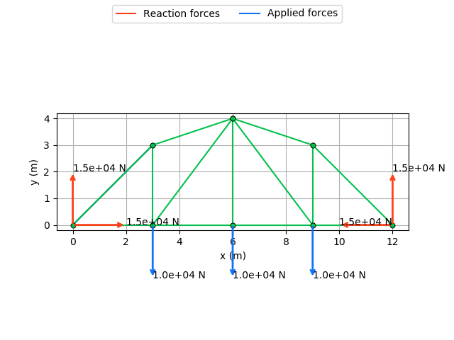
The applied and reaction forces in the truss are depicted in the trussForces.png file.

