This repository contains C++ code for implementation of PID controller, to derive steering angles for a car to drive around a circular track. This task was implemented to partially fulfill Term-II goals of Udacity's self driving car Nano degree program.
A critical module in the working of any robotic system is the control module. Control module defines the action, which the robotic system performs in order to achieve a task. These actions can vary on type of the system and type of the task. For e.g.: A simple mixer grinder's control module only controls the speed of rotating motor. A little more complex system such as a Remote Controlled (RC) car needs a control module to move forward, backward and turn. Highly complex systems such as prosthetic arms, self driving cars, product manufacturing factory units require control modules for multiple tasks at the same time.
One of the basic implementation of a control system is a Proportional (P), Differential (D), Integral (I), together, a PID controller. PID controller is the most popular controller and is used in applications across domains.
The basic principle of working of a PID controller is to satisfy a boundary value problem. Most common examples of such problems are either minimization of the total error in the system or maximization of the total gain in the system. These error or gain problems are represented mathematically and are used to govern the effect to P, I and D components of a PID controller. These components are described below:
- Proportional (P) component: Mathematically, the P component establishes linear relationship with the problem. The effect of P component is in proportional to the value of problem at the current time step. For e.g.:, if the problem is to minimize the error in the system at current time step, the value of P component is given by the formula:
αp = -Kp * error

where, Kp is a tuning parameter known as the proportional gain. The negative sign in the beginning signifies that P component is used to cancel the effect or error, or in other words, reduce it.
- Differential (D) component: Mathematically, the D component establishes linear relationship with the rate of change of problem. The effect of D component is in proportional to the rate of change problem from last time step to current time step. For e.g.:, if the problem is to minimize the uncertainty in the system, the value of D component is given by the formula:
αd = -Kd * d(error)/dt

where, Kd is a tuning parameter known as the differential gain. The negative sign in the beginning signifies that D component is used to cancel the effect or rate of change of error, or in other words, reduce it. The D component is used to minimize sudden changes in the system.
- Integral (D) component: Mathematically, the I component establishes linear relationship between the average value of problem over time. The effect of I component is in proportional to the average value of problem from the beginning of time to the current time step. For e.g., if the problem is to minimize the error in the system, the value of I component is given by the formula:
αi = -Ki * ∑ error

where, Ki is a tuning parameter known as the integral gain. The negative sign in the beginning signifies that I component is used to cancel the effect or average error, or in other words, reduce it. The I component is used to correct systemic bias.
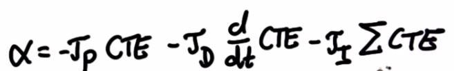
When all components are used, the mathematical equation is given by:
α = (-Kp * error) + (-Kd * d(error)/dt) + (Ki * ∑ error)
where, α is the control input to the system, often known as the actuator input.
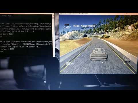
In this project, a PID controller was implemented to drive a car around circular track having sharp left and right turns. A good solution would help the car stay in the center portion of the lane and take smooth left and right turns without touching or running over the edges of the lane (considered as risky in case humans were travelling in such a car). Project goals were briefed in the video below:
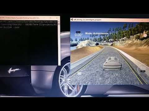
Simulation of a circular track was achieved in the Udacity's self driving car simulator. The simulator measured the cross track error (cte) between the lateral position of car and the center of the lane. This error was communicated to C++ code with the help of uWebSockets library. The cte was then used to calculate P, I and D components of the controller governing the steering angle of the car.
The final implementation consisted of following major steps:
- Cross track error (cte) recorded by the simulator was used to develop the mathematical equation for calculating steering angle of the car. This is given below:
-
The major task in this implementation was to tune the Kp, Ki and Kd gain parameters. This was done using manual tuning in the beginning and followed by fine tuning by using Twiddle or Gradient Descent. This process is listed in the following steps.
-
In the initial step, the I and D components were switched off and only the P component was used to drive the car. This was done by setting the Ki and Kd parameters to 0. The car was allowed to drive along the track. The value of Kp was tuned manually to help the car stay on the track for at least 20% of the total track length, as long as it doesn't cross the edge of the track. This is demonstrated in the video below:
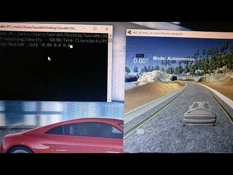
As expected, the car could only stay for around 20% on the track due to oscillations in the run. These oscillations were created due to overshoot phenomenon created by P component, best explained by Sebastian Thrun in this video. These oscillations were prevented by introducing the D component as described in next step.
- In this step, a PD controller was used. The I component was still switched off by setting the value of Ki to zero. The value of Kp was as tuned from step 3 and the value of Kd was tuned manually to keep the car on track for most of the length of the track. This is demonstrated in the video below:
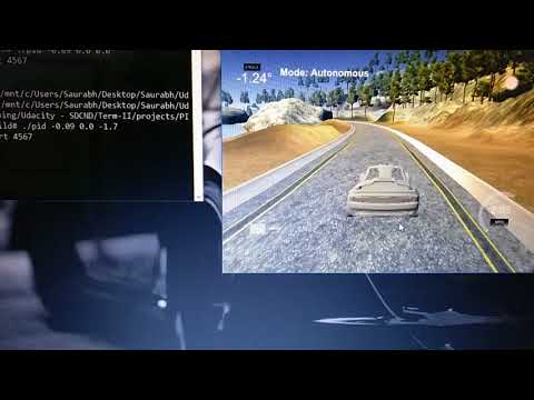
As seen, the car was able to stay on the track and drive successfully for most of the portion. However, it was observed that the car wouldn't stay in the center of the lane and often drift to the edges. This resulted in very sharp turns which is certainly not desirable in case a human was sitting inside the car. As described in next step, introduction of I component solved this problem.
- Due to some kind of systemic bias and uncertainty in the system, the car would often drift to the edges of the lane. This undesired behavior was corrected by introducing the I component. The value of Kp and Kd were as tuned from step 3 and step 4 respectively. The value of Ki was tuned manually to restrict the car drifting away from center of the lane. The final effect of use of PID controller is demonstrated in the video below:
- Gain parameters were then fine-tuned by using vanilla Gradient Descent algorithm, also known as Twiddle. In this process, manual tuned values from step 3, 4 and 5 were taken as a starting point. Each of the gain parameters Kp, Ki and Kd were tuned one at a time. For e.g., Ki and Kd were kept constant during the fine tuning of Kp and the overall error in the system was minimized. To optimize the algorithm, the car was driven only for 500 time steps after which the simulator was reset to bring back the car in original starting position. Few results obtained while fine tuning are given below:
Fine tuning of Kp -> Ki = -0.001, Kd = -1.0
  Run 1                                Run 2

  Initial Kp = -0.2                    Initial Kp = -0.1
  Initial delta_p = -0.1               Initial delta_p = -0.05
  Tolerance = 0.05                     Tolerance = 0.001
  Best error achieved = 32.231         Best error achieved = 10.002
  Final Kp = -0.1109                   Final Kp = -0.091
Fine tuning of Kd -> Kp = -0.091, Ki = -0.001
  Run 1                                Run 2

  Initial Kd = -1.0                    Initial Kd = -1.5
  Initial delta_d = -0.1               Initial delta_d = -0.05
  Tolerance = 0.05                     Tolerance = 0.001
  Best error achieved = 8.112          Best error achieved = 4.935
  Final Kd = -1.54                     Final Kd = -1.693
Fine tuning of Ki -> Kp = -0.091, Kd = -1.693
  Run 1                                Run 2

  Initial Ki = -0.001                    Initial Ki = 0.0003
  Initial delta_i = -0.005               Initial delta_i = -0.0005
  Tolerance = 0.0005                     Tolerance = 0.0001
  Best error achieved = 4.13             Best error achieved = 3.225
  Final Ki = -0.0003                     Final Ki = -0.0005
Final values of tuned parameters were: Kp = -0.091, Ki = -0.0005, Kd = -1.693. Gain parameters are just absolute values and the negative sign added comes from the equation of a steering angle using PID controller stated in step 1.
PID controller used to derive the steering angles for a car moving on a circular track was implemented successfully. The car could stay close to the center of the lane and take smooth left and right turns along its path.
-
cmake >= 3.5
-
All OSes: click here for installation instructions
-
Linux and Mac OS, you can also skip to installation of uWebSockets as it installs it as a dependency.
-
make >= 4.1(mac, linux), 3.81(Windows)
- Linux: make is installed by default on most Linux distros
- Mac: install Xcode command line tools to get make
- Windows: Click here for installation instructions
- Linux and Mac OS, you can also skip to installation of uWebSockets as it installs it as a dependency.
-
gcc/g++ >= 5.4
- Linux: gcc / g++ is installed by default on most Linux distros
- Mac: same deal as make - [install Xcode command line tools]((https://developer.apple.com/xcode/features/)
- Windows: recommend using MinGW
- Linux and Mac OS, you can also skip to installation of uWebSockets as it installs it as a dependency.
-
- Run either
install-mac.shorinstall-ubuntu.sh. This will install cmake, make gcc/g++ too. - If you install from source, checkout to commit
e94b6e1, i.e.Some function signatures have changed in v0.14.x.git clone https://github.com/uWebSockets/uWebSockets cd uWebSockets git checkout e94b6e1
- Run either
-
Simulator. You can download these from the Udacity simulator releases tab.
-
Execute every step from ./install-ubuntu.sh. This will install gcc, g++, cmake, make and uWebsocketIO API.
-
Manually build the project and run using: a. mkdir build && cd build b. cmake .. c. make d. ./pid
-
Run the Udacity simulator and check the results