9-DOF IMU using ESP32 and MPU9250
One picture is worth a thousand words!
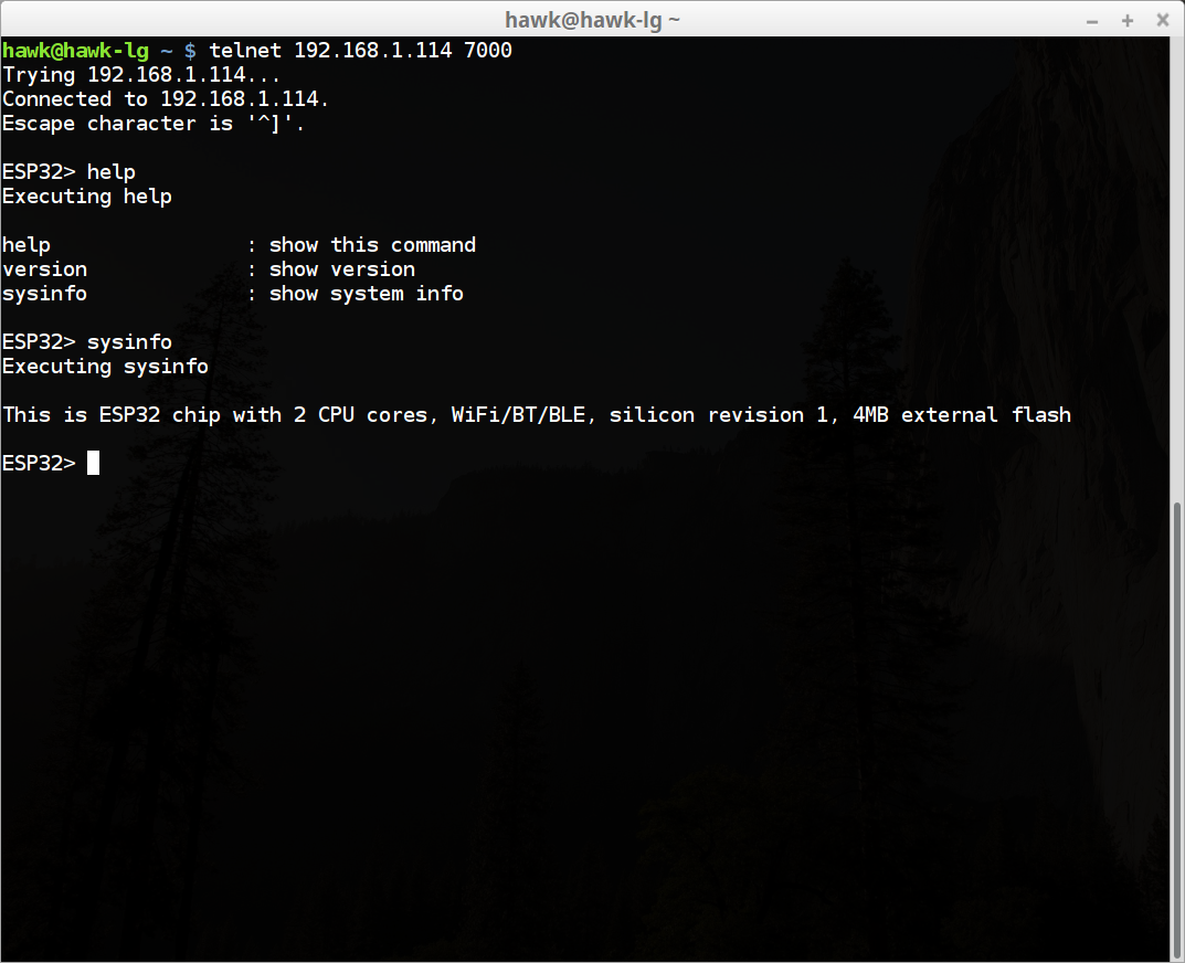
CLI is implemented. Now you can access ESP32 via telnet.
By the way, the code might seem a bit intimidating at first. But that is how I think networking code should be written. Everything should be an event using an simple event loop. Otherwise you wouldn't be able to handle the complications and the concurrency in the end. Just my 10 cents on it!
just getting started, folks!
| Purpose | Pin # |
|---|---|
| Green LED | 22 |
Check this out
To develop a firm understanding on what's going on behind the scenes, I always care about system startup process. Actually this is well explained here
To sum it up,
-
ROM bootloader loads second-stage bootloader in SPI Flash to RAM from flash offset 0x1000
- Second-stage bootloader source is available at components/bootloader directory of ESP-IDF.
- Partition table is at 0x8000 of SPI flash.
- It is interesting to note that second-stage bootloader initializes MMU!
- Also it is interesting to note that SPI flash memory is memory mapped by MMU and can be read via normal memory read.
-
Second-stage bootloader loads partition table and main application image
-
main app executes
Application Memory Layout. The chip itself is not that simple. ESP32 comes with 520 KiB SRAM. Most boards I know have 4 MB SPI flash.
| Type | Note |
|---|---|
| IRAM | instruction RAM. a part of internal SRAM0. fast execution & for ISRs |
| IROM | instruction ROM. SPI flash. |
| RTC fasl | for code that has to run after wake-up from deep sleep. |
| DRAM | data ram. of course. |
| DROM | read only data in SPI flash. |
| RTC slow | blah blah blah |
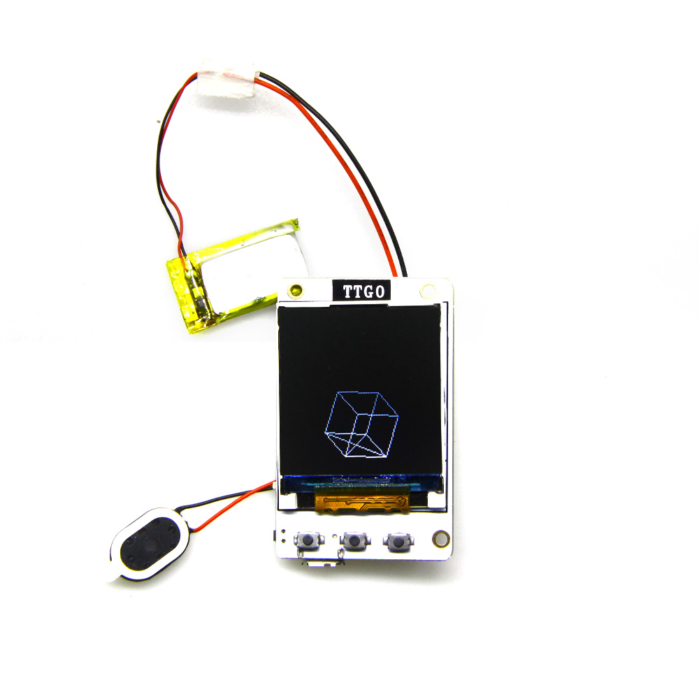
According to the shcematic, ST7735 TFT is connected to ESP32.
| Name | Pin # |
|---|---|
| MOSI | 23 |
| SCK | 5 |
| CS | 16 |
| MOSI | 23 |
| CMD/DATA | 17 |
| RESET | N/A |
One more thing to note is there is no pin to control LCD backlight with. It can be quite annoying.
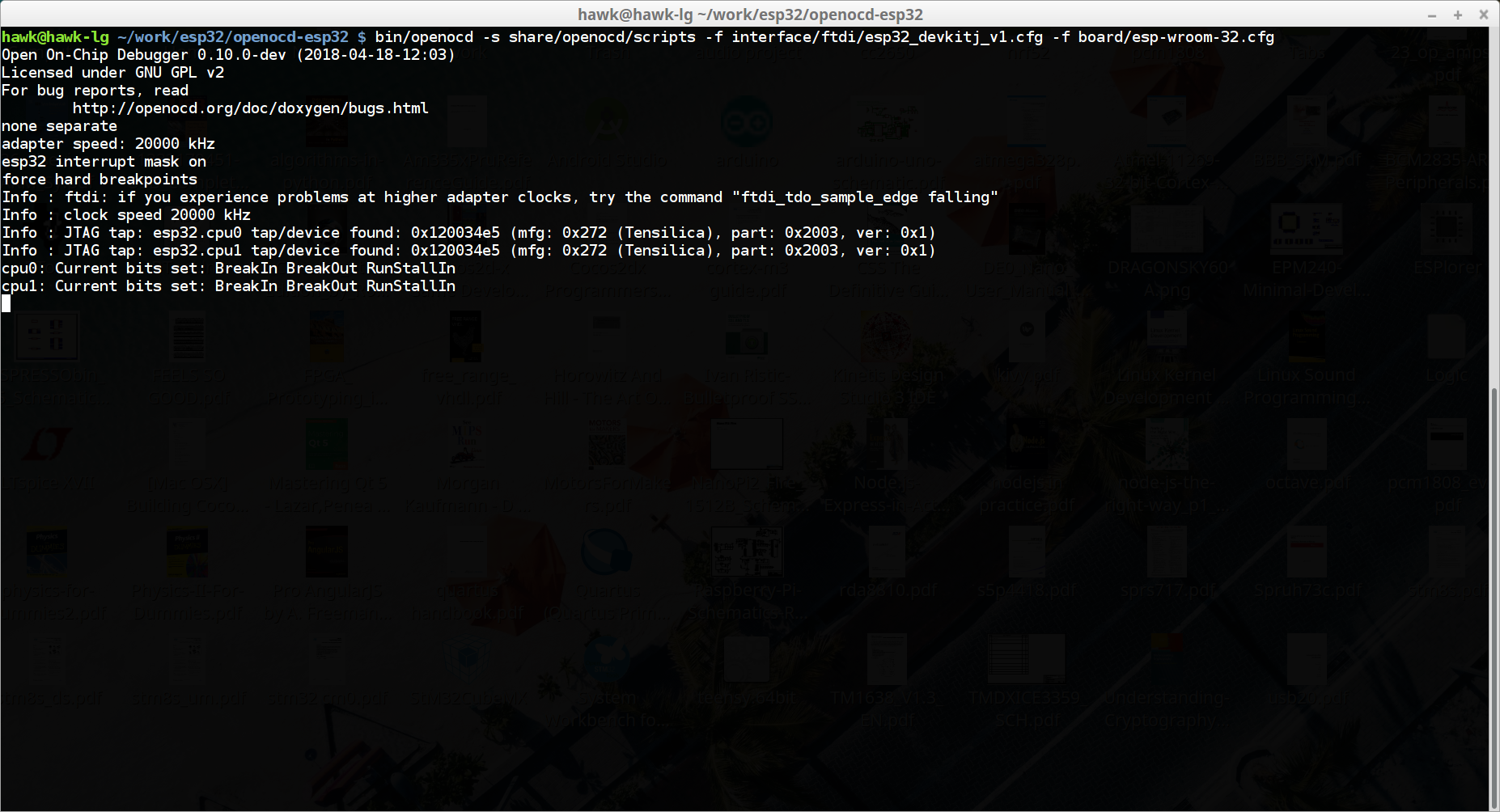
- get openocd
- FTDI Connection as shown below
| FT2232HL | ESP32 | Purpose | SDIO Pin |
|---|---|---|---|
| ADBUS0 | 13 | TCK | DAT3(2) |
| ADBUS1 | 12 | TDI | DAT2(1) |
| ADBUS2 | 15 | TDO | CMD(3) |
| ADBUS3 | 14 | TMS | CLK(5) |
| GND | GND | GND | VSS2(6) |
| VIO | 3V3 | 3V3 | NC |
Problem is pin 12/13/14/15 are used for SDIO, which means
- you can't use JTAG interface while using Micro-SD slot
- we need a some special SDIO adapter to connect FT2232H and ESP32
And finally found a wonderful sdio adapter.
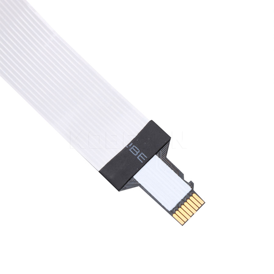 Check it out at Aliexpress
sdio adapter pin mapping 1 Left, 13 Right
| SDIO Side | Adapter Side | Note |
|---|---|---|
| 1 | 1 | TDI |
| 2 | 3 | TCK |
| 3 | 5 | TDO |
| 4 | 7 | VDD (Do Not Connect) |
| 5 | 9 | TMS |
| 6 | 2,4,6,8,10,12 | GND |
| 7 | 11 | NC |
| 8 | 13 | NC |
Got my order from China and here we go
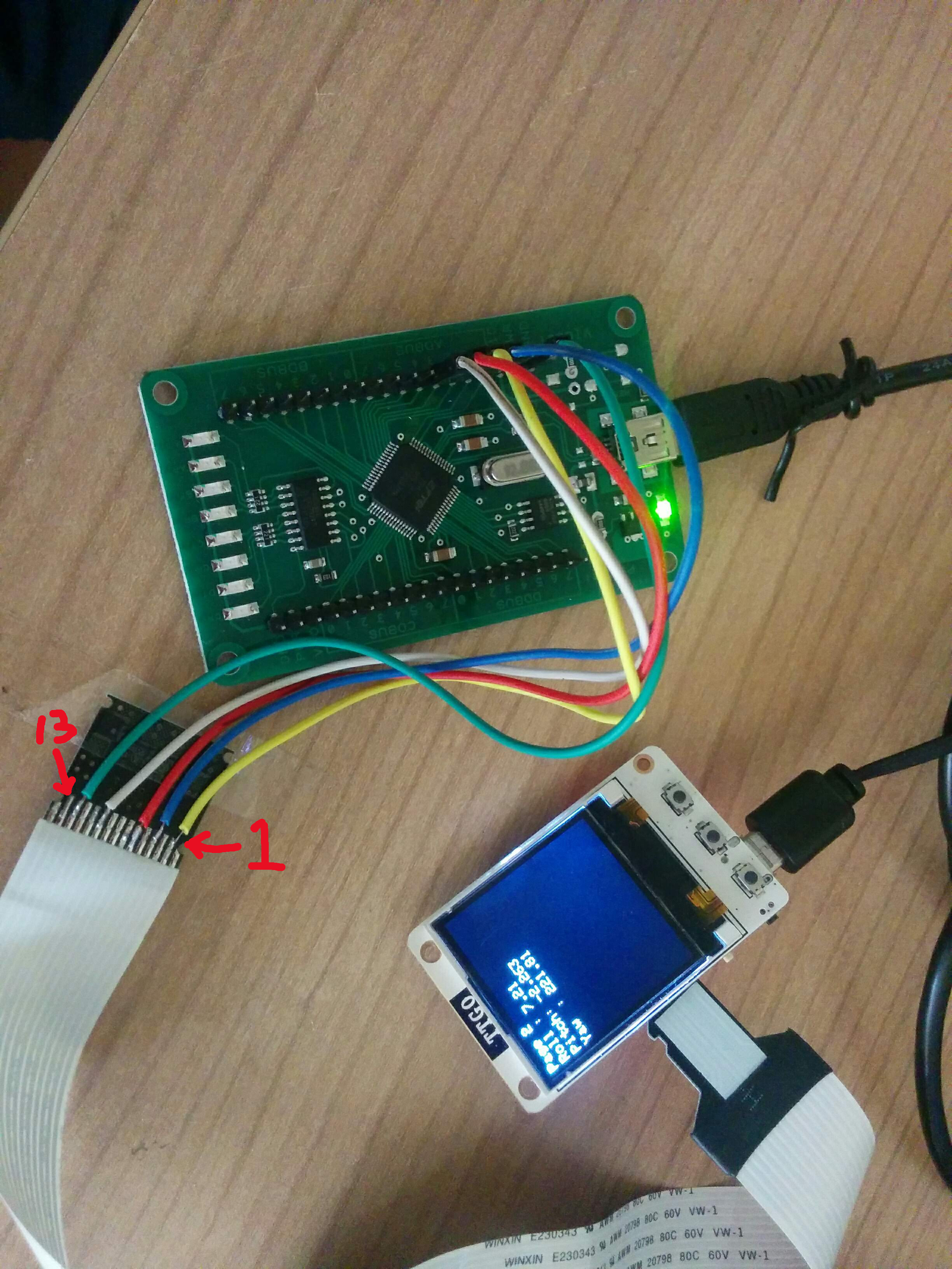
esptoo.py read_flash 0x8000 0xc00 partition.img
esptool.py read_flash 0x0000 0x400000 backup.img
esptool.py read_mac
esptool.py run
esptoo.py write_flash address your-bin
partition table is at 0x8000 with size 0xc00
gen_esp32part.py --verify binary_partitions.bin input_partitions.csv
gen_esp32part.py --verify input_partitions.csv binary_partitions.bin
Espressif ESP32 Partition Table
| Name | Type | SubType | Offset | Size |
|---|---|---|---|---|
| nvs | data | nvs | 0x9000 | 0x6000 |
| phy_init | data | phy | 0xf000 | 0x1000 |
| factory | app | factory | 0x10000 | 1M |
