I wanted to use an RGB Illuminated Rotary Encoder for a project but I didn't know how they worked. This project is a simple test project to explore the hardware and functionality.
| Components | Src | Cost | Notes |
|---|---|---|---|
| Arduino Nano | 1 | £2.41 | V3 Compatible ATMEGA328P CH340 |
| Rotary Encoder Breakout | 1 | £3.99 | Board - Illuminated (RG/RGB) |
| Rotary Encoder RGB | 1 | £4.99 | Illuminated, came with knob. |
| Resistor | ? | ? | 10KR |
| Breadboard | ? | ? | One of many |
| Bread board wires | ? | ? | Several |
- Ebay.co.uk - although I bought the components last year, so prices may no longer be accurate.
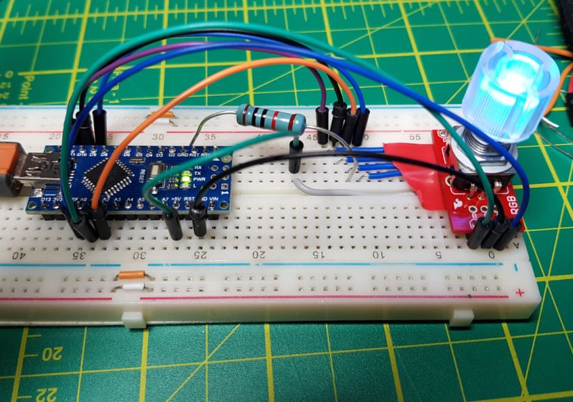
This is the breadboard construction, it's not very tidy but it works.
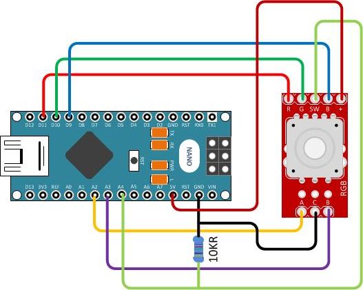
And here is a tidier diagram of the connections between the RGB Rotary Encoder and Arduino Nano.
Note the resistor pulling down the wire from 'SW' on the Rotary Encoder Breakout board. I found this necessary to stop the input floating around.
Ardino UNO Tutorial 6 - Rotary Encoder
This tutorial gave me the basics of reading the encoder part, and is worthwhile to understand how the encoder works.
RGB ROTARY ENCODER TEST (Arduino)
This youtube video by TETRASTYLE was interesting but the link to the sample code helped me understand how to control the RGB and Switch.
-
Run the example code attached to the Arduino Serial Monitor
-
The program will output instrumentation indicating when the setup function has started and completed.
-
It will then output the analogue PWM output values for the 'R', 'G' and 'B' pins.
-
Turning the encoder knob will increment or decrement the first output value in steps of 15, up to 255 or down to 0, where it will circle around.
-
Pressing down on the knob will switch to the next PWM value so that it can be incremented or decremented.
Example Serial Output...
    Setup started.
    Setup completed.
   R:255, G:240, B:255
   R:255, G:255, B:255
   R:255, G:0, B:255
   R:255, G:0, B:240
   R:255, G:0, B:255
   R:255, G:0, B:0
The encoder part worked out of the box with no issues.
However, the RGB LED and push Switch gave me a lot of trouble. I'm not an electrical engineer at all, so I learned quite a bit I think.
I couldn't find any examples of how to connect the RGB LED to an Arduino, despite TETRASTYLE's code and video. I found the schematic for the board and it indicated the '+' was 'common', which I took to mean ground.
But when I connected that pin to Ground and the 'R', 'G', and 'B' pins to PWM output pins of the Nano, I got nothing.
Playing around I eventually worked out (by trial and error) that the '+' is a common +5V input and connecting the 'R', 'G' and 'B' pins to Ground is what illuminated the respective LED!
The interesting thing is that I could still use the PWM output pins to drive the LED, but in reverse. That is, an output of 255 on a PWM pin would turn the associated LED colour off, where as an output value of 0 would allow the LED to be at full brightness.
TETRASTYLE's sample code shows the same thing, I just didn't understand it at the time.
Pressing the encoder knob down should activate the 'SW' pin. I had it connected as a simple digital input but the problem was that when I rotated the knob it was as if the switch was activating all the time.
Putting a PRINT on the pin read value showed the issue.
- When pushed down it was a steady 1 (HIGH)
- When not pushed down, the input floated between 1 and 0 (HIGH and LOW).
The fix was to add a 10KR Resistor between the SW pin and ground. You can configure Arduino Inputs to be Pullup inputs (e.g. HIGH when they float) but not Pulldown inputs (LOW when the float). This is what adding the resistor does.

