I bought the arcade1up Street Fighter cabinet with the intention of modding it to turn it into a multi-system emulation machine. For $199 (got it on sale), it's hard to beat versus building your own and when I read online that you could reuse most of the hardware in it, I decided to jump in.
I mostly followed ETA Prime's youtube tutorial and then I added my own changes. If you're trying to add in your own stuff, mind that there's a ton of outdated info on the internet. My mods here are the simplest way I could achieve the behavior I wanted.
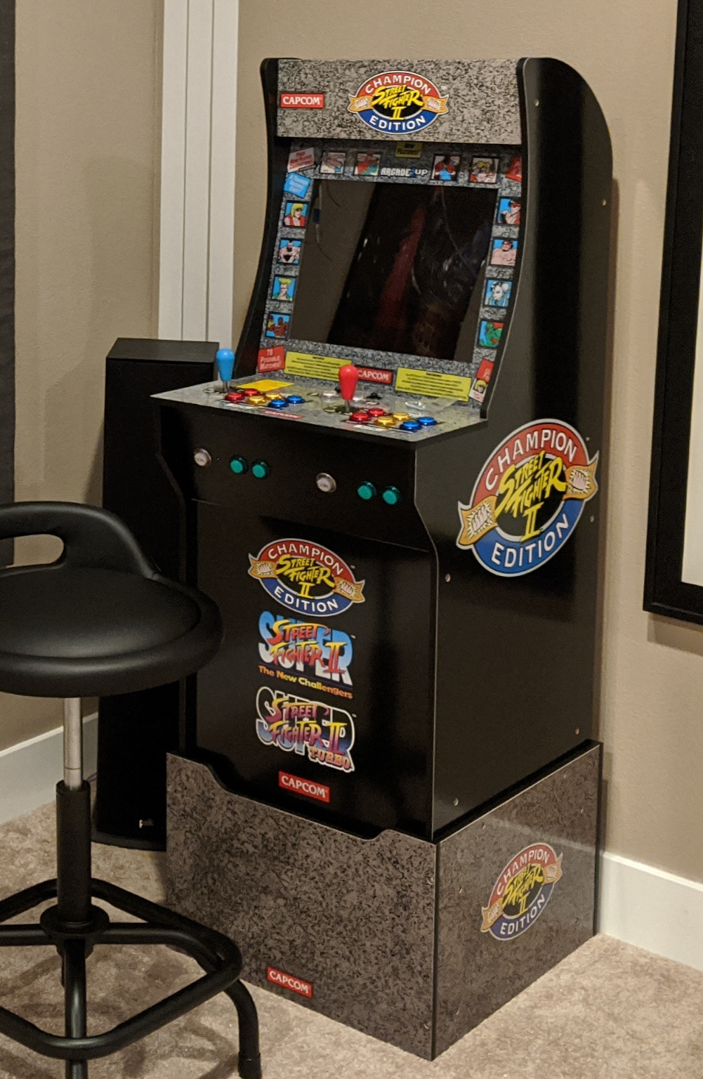
This is a (bad) picture of the end result from the outside:
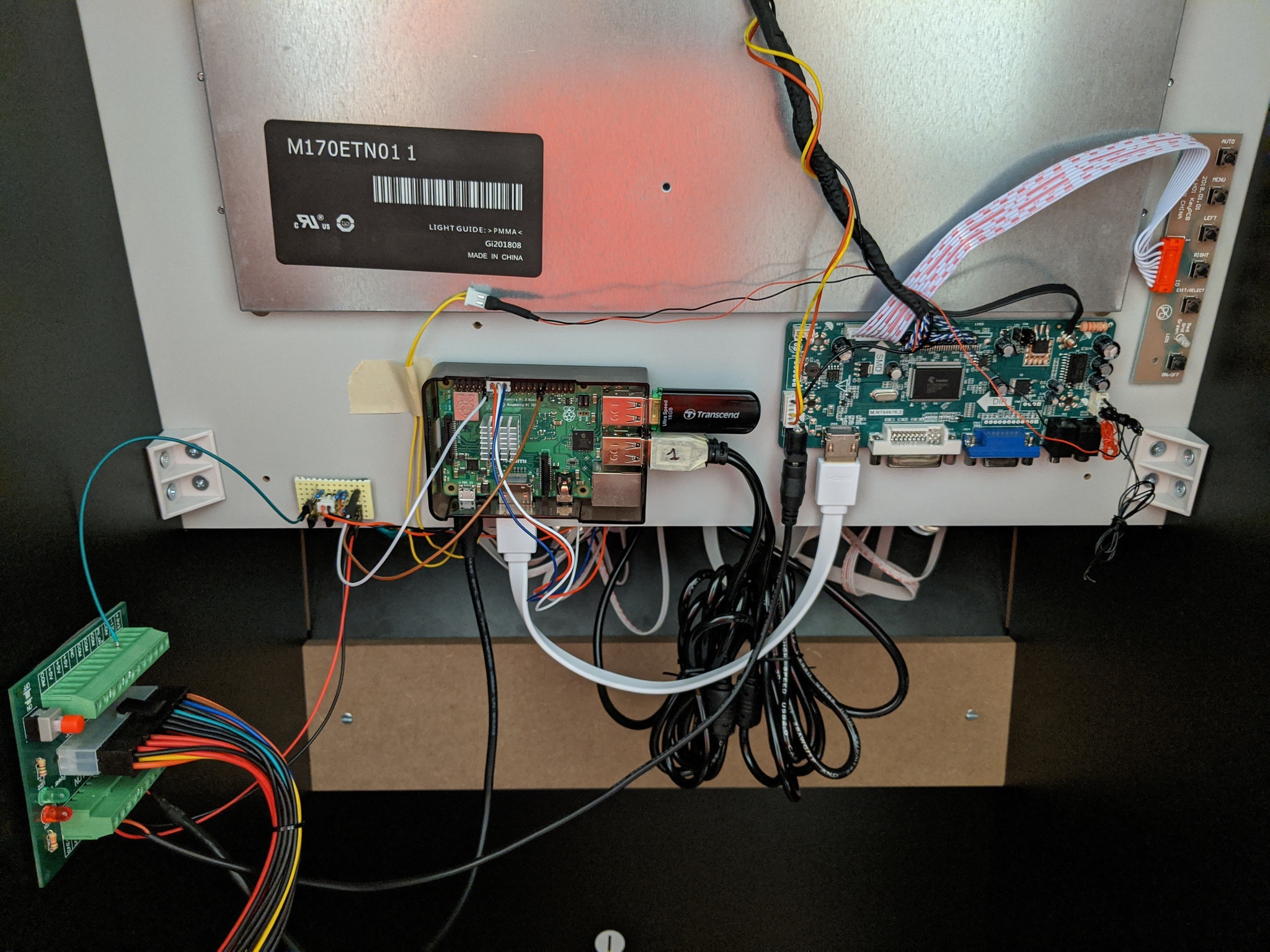
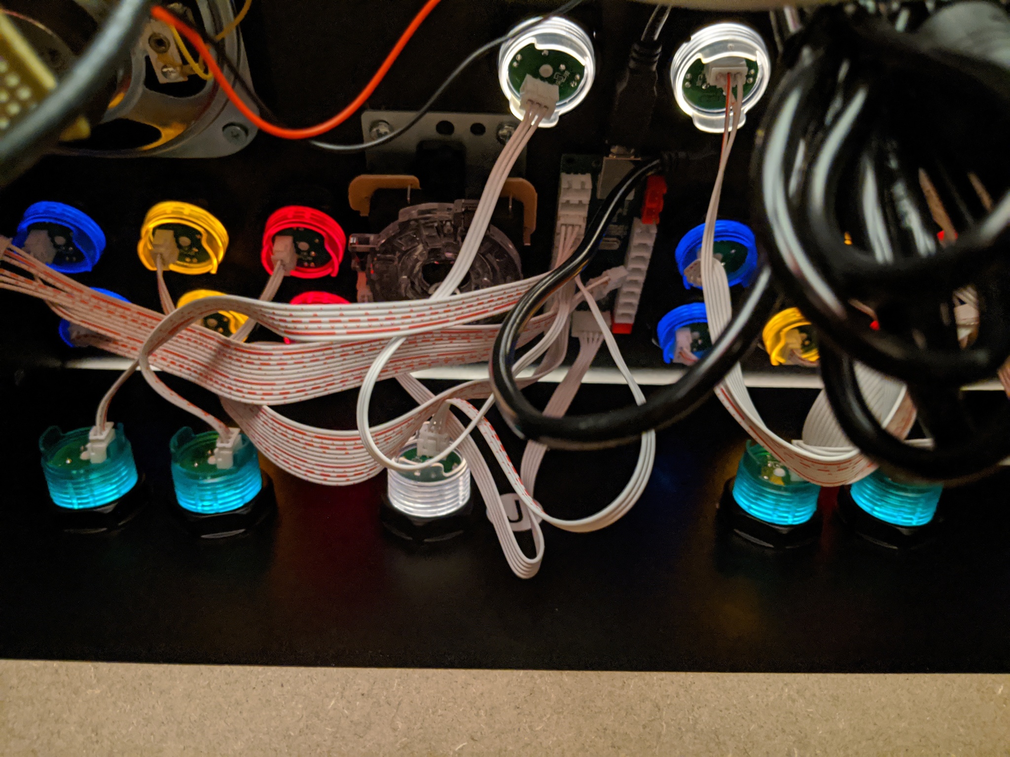
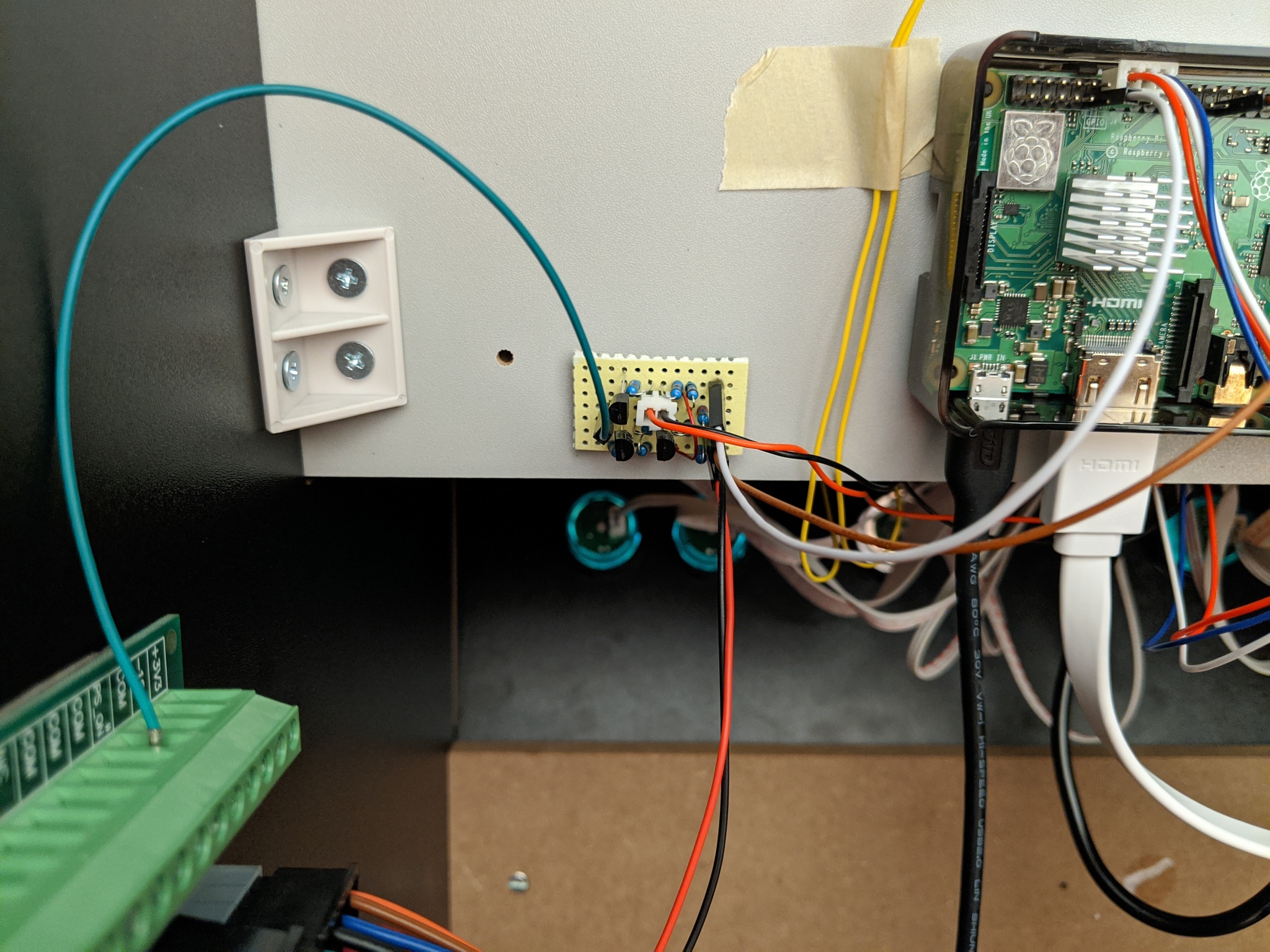
And this is a general picture of the guts (more detailed ones below):
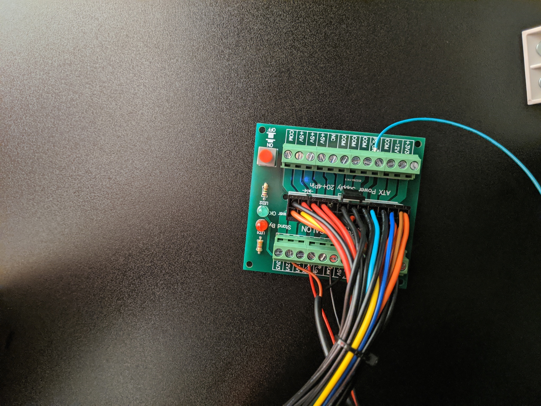
Electronics-Salon 24/20-pin ATX DC Power Supply Breakout Board Module.
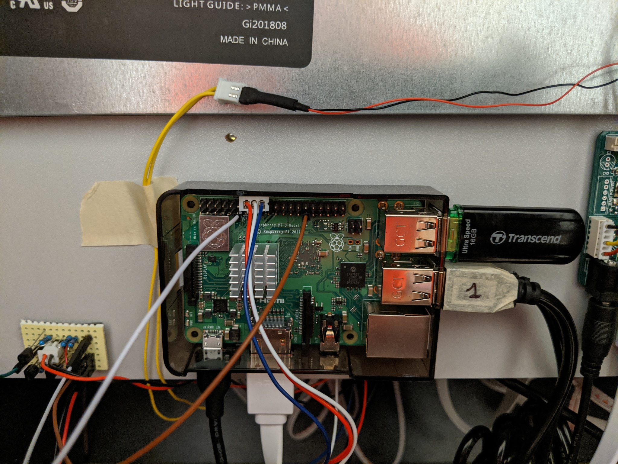
Just followed the video. I used a spare 3B+ that I had around. I've read somewhere that the 4 is now supported and much more performant, specifically for 3D games. I'm not using an SD card, but I'm booting off a 16 GB USB drive that I had around too (I've been pretty unlucky with SD cards in the past).
I used RetroPie as OS. I've also read that Lakka is based off of LibreElec, which runs on a read-only partition and it might be much more resilient to unexpected power downs and other issues, but the interface is significantly different.
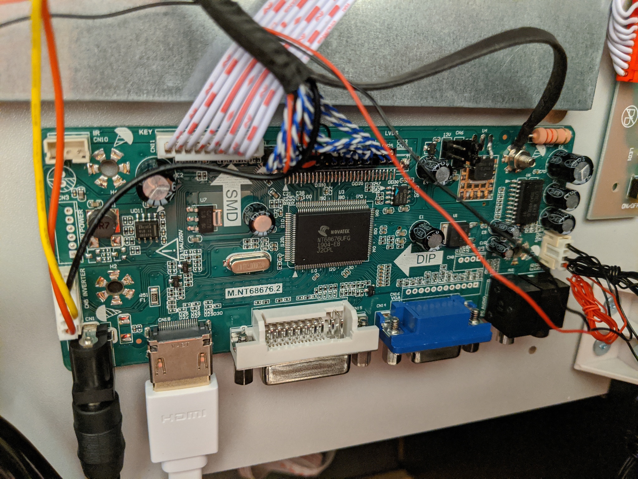
This is pretty easy, just follow the video and that's it. It's just a matter of unscrewing the original controller board, removing the connectors, screwing the ground wire in the right place and plugging the 2 connectors back in the right place in the new controller board. With that, your cabinet will have a proper HDMI input port.
Instead of going with ETA Prime's idea of adding an external amplifier, I just decided to use the display controller built-in amp. It's just 1 Watt, but honestly, the stock speaker is crap anyway, and 1 W is plenty loud for me (if you're doing this for a game room where you'll throw parties and stuff, it might not be enough, in which case an external amp and a pair of 4 inch speakers would be the way to go).
I just got one of the extra cables that came with the display controller that had the right connector and soldered a couple pin terminals to it. According to the controller pinout, the center 2 pins are ground and the side ones are the left and right output (ideally, the center ones should be different per speaker, but the documentation isn't clear to me). The cable, only had one of the center cables connected, so I used the signal one on the same side, to play it safe. Plug it in the female speaker connector and you're game.
The cabinet only has a single speaker, so I changed the alsa configuration to downmix everything to mono. That way, games in stereo sound bad, but at least, all sounds come through. Instead of actually testing with a game, I played a stereo wav file through aplay from the command line to make sure this worked. You can find the file here (got it from some random site).
You can see the connection to the controller in the picture above for the screen mod and the speaker connection in the general view.
I pretty much followed the video for this one. There are other ways to do this, but honestly, USB controllers and a new set of buttons is t he easiest one. Just be careful when adding the sticks, to make sure they are centered, and choose a pretty combination of colors for the buttons. I chose a set of buttons with 3 pin terminals, which removes some of the clutter, but on the other hand, you can't disable the LED lighting if you want (or maybe you can in the controller itself, I haven't explored this, but there's a 'Mode' button which documentation says it changes the mode, whatever that means). I like mine lit, but you might not. Also, be careful when sticking the controllers to the underside, to make sure cables properly fit (I had to move one out of the way, because my controllers use standard USB connectors instead of PCB ones).
Instead of defacing the controller panel to add the select (Coin) buttons, I decided to add them in the panel below it. Advantage is that it's a much thinner one, and the disadvantage is... that it's a much thinner one. It kind of warps when pushing the buttons, but since these aren't supposed to be used much, it works for me. My button set came with a pair of extra buttons (8 per player), and again, instead of adding them to the main controller, I put them below as well. I don't play any games that use 8 buttons per player, so having them out of the way is also fine. I mapped them to fast-forward and slow-motion (or rewind, depending on the game). It's a bit annoying to have to move my hands so much for this, but it works ok.
TODO: Add diagram of the panel holes.
This is basically a three position switch, with a common terminal (connected to the red wire) and 2 other terminals connected to the blue (volume -) and white (volume +) wires. I think this is actually a double pole switch, but I haven't actually checked, in which case you could do fancier stuff, I guess.
To make this work, I just connected the 3 pin terminal to pins 14-16-18 (Red-White-Blue), so red wire (common) goes to ground, white (volume +) goes to GPIO 23 and blue (volume -) goes to GPIO 24.
Then I tried using the gpio-keys device tree overlay but it didn't do exactly what I wanted (it generates an input device per GPIO pin and it doesn't support repeat), so I created my own overlay, which you can find in the repo. This overlay creates a new input device with 2 keys mapped to VOLUMEUP and VOLUMEDOWN events. To manage the generated events, I used the already installed triggerhappy, adding a single config file to change the global volume by 0.5 dB increments. In this way, if you keep the physical button in the center, volume stays constant, if you flip it to the left, volume goes progressively down and up if you flip it to the right. If you don't like the speed, you can change the dB increments.
I've seen a bunch of projects out there do this same thing in a much more complicated way, using esekeyd, or writing a piece of Python code. Just use triggerhappy and the overlay (if the default gpio-keys overlay supported key repeat I would've used it even if it created multiple input devices).
A fancier mod would be swapping this button for one with automatic return to center. I'm not bothered by it, though, so I didn't do it.
The way the package is configured, it runs as nobody which stops it from changing the global volume. I changed the startup config to make it run as the pi user.
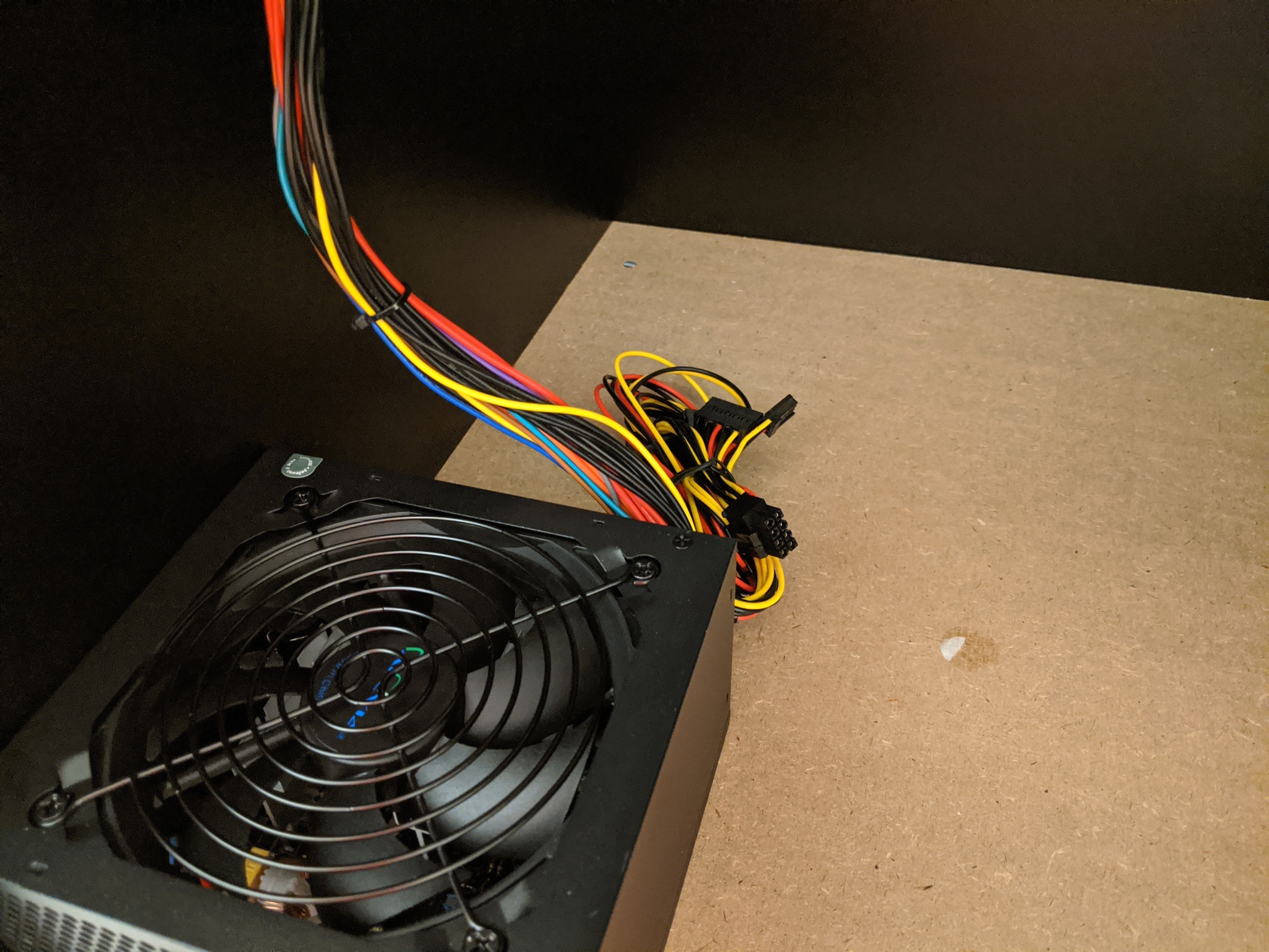
I didn't want a power strip inside the cabinet, so I decided to power everything from a cheap ATX PSU, which would also allow me to control power for the next mod. To make things easier on me, I decided to use an ATX breakout board, so that I didn't have to modify the PSU itself. It's expensive, relative to everything else, but it made my life so much easier (and it will be awesome when the PSU fails, just plug a new one, and back in business).
This is where I had the most fun. First my requirements:
- Use an ATX PSU to control power to the rest of the components (via
PS_ON). - Working power switch in the control panel
- RPi needs to be completely powered off when arcade not in use (no half-assed halt mode).
- Blindly powering off the RPi is a no-no
- Power control can run off the 5VSB rail (always on 5V).
So I used two very nice device tree overlays for this: gpio-poweroff and gpio-shutdown.
gpio-poweroff triggers a gpio line when the CPU is about to be halted (so everything else has been properly shut down at that point), and gpio-shutdown acts like an input signal that triggers an OS shutdown (which will eventually result in the gpio-poweroff triggering).
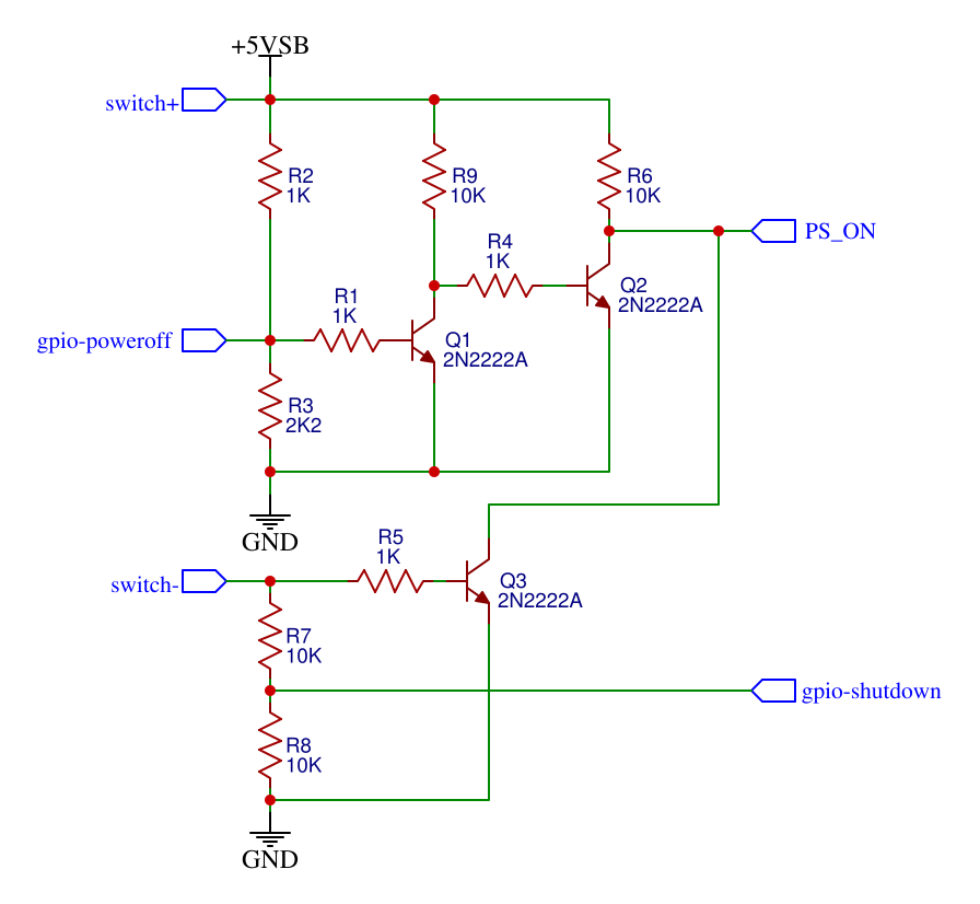
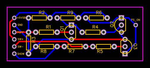
I need some custom electronics to get this to work, so I designed a circuit with two distinct parts.
To trigger this input, I need to connect the 5VSB line to the physical power switch (switch+) and the other side (switch-) goes to a voltage divider that will give me about 2.5V when the switch is in the on position and 0V when it's off. The voltage divider is there to protect the GPIO since the Pi is only 3.3V tolerant.
I configured the overlay like this:
dtoverlay=gpio-shutdown,gpio_pin=17,gpio_pull=off,debounce=200
The default config is active_low (triggers on falling edge), so when the switch is in the on position and it's moved to off, the pin will go from 2.5V (logical 1) to 0V (logical 0), triggering the shutdown. I used pin 17 and disabled pull resistors (since the external circuit already provides pulldown). Set debounce to 200ms, just in case the switch goes funky.
This was even more fun. The behavior I wanted was mostly a logical OR of the switch in the on position and the poweroff signal not being triggered. PS_ON is active low, so basically I needed to invert the switch input (active high) via Q3, and on open collector this is one side of the OR.
The other side is slightly more interesting. I wanted to set up the output pin as active high (because according to the documentation, active low is a lot more complicated. Since PS_ON is active low, a high signal will turn off the PSU, so I need to follow the poweroff signal from the Pi. 2 transistors later (Q1 and Q2), this is what I got. The collector of Q2 combined with the collector of Q3 and a pullup resistor R6, output exactly the signal I want.
The overlay configuration looks like this:
dtoverlay=gpio-poweroff,gpiopin=5
I used GPIO pin 5 because it has a natural pullup. Together with the external pullup/pulldown combo, if the pin is floating, Q1 sees a logical high signal, so the output is also high and the PSU is off.
In summary: if RPi and switch are off, gpio-poweroff is floating (pulled up) and switch- is floating (pulled down), so both Q2 and Q3 are switched off and PS_ON is high via R6, so the PSU is off (cabinet is in the power off state). When I move the switch to on, Q3 switches on and inconditionally pulls PS_ON down, turning the PSU on (cabinet enters the turning on state). When the Pi boots the kernel, gpio-poweroff is pulled down, so Q2 switches on, pulling PS_ON down (but it's already down from the switch), this gets the cabinet in the power on state (you can play now!). When you move the switch to the off position, Q3 turns off, but PS_ON is being held down by Q2. RPi gets the shutdown signal and starts the OS shutdown sequence (cabinet in turning off state). When the kernel is done, it triggers the gpio-poweroff pin high, and Q2 turns off, while R6 pulls PS_ON high, and the PSU turns off (this is the power off state again). Phew!
I built this circuit in a prototype board and used it as is. I also created a PCB for it, but I haven't tested it, so it might have some error.
If you want it built, you can download the Gerber files here ($2 in JLCPCB will get you 5 boards).
Just followed the instructions in the RetroPie FAQ.
I still get a couple lines from the kernel at boot time, probably related to the fact that I'm running the OS from an USB drive instead of the SD, but I can live with them.
I enabled the hardware watchdog on the RPi. This is pretty easy to do, you just have to enable support in /boot/config.txt by adding a line like this:
dtparam=watchdog=on
And then make systemd send a periodic heartbeat by changing the following 2 lines in /etc/systemd/system.conf:
RuntimeWatchdogSec=10
ShutdownWatchdogSec=1min
This way, if the kernel crashes for whatever reason, the Pi will reboot in about 15 seconds.
You should also enable autoreboot on kernel panic by adding this line to /etc/sysctl.conf:
kernel.panic = 5
This is by far, the biggest source of misinformation around, with lots of people trying to do this via the old watchdog package or some other weird way. A couple config changes is all you need, don't go installing stuff on your Pi.
I found a nice arcade1up + RetroPie splash image in a github repo that I just forked.
