
This repository provides an Atmel Studio solution with a bare metal code example for an LED blink driven by a timer overflow interrupt (Timer/Counter Type A). This example demonstrates a simple toggling of a LED connected to the PC6 (on-board user LED) with an on/off cycle period of 1 second implemented through the use of an interrupt generated by the overflow of TCA0. The on-board user LED on the development board will toggle each 500 milliseconds.
More details and code examples on the AVR128DA48 can be found at the following links:
- Atmel Studio 7.0.2397 or newer (microchip.com/mplab/avr-support/atmel-studio-7)
- AVR-Dx 1.0.18 or newer Device Pack
- AVR128DA48 Curiosity Nano (DM164151)
The AVR128DA48 Curiosity Nano Development Board is used as test platform

The following configurations must be made for this project:
TCA0:
- Normal mode
- Input clock Main Clock (4MHz) /256
- Overflow interrupt enabled
- Period 0x2000
CPUINT:
- Global interrupt enabled
| Pin | Configuration |
|---|---|
| PC6 (LED0) | Digital Output |
-
Open the AVRDA_LED_blink_interrupt.atsln solution in Atmel Studio
-
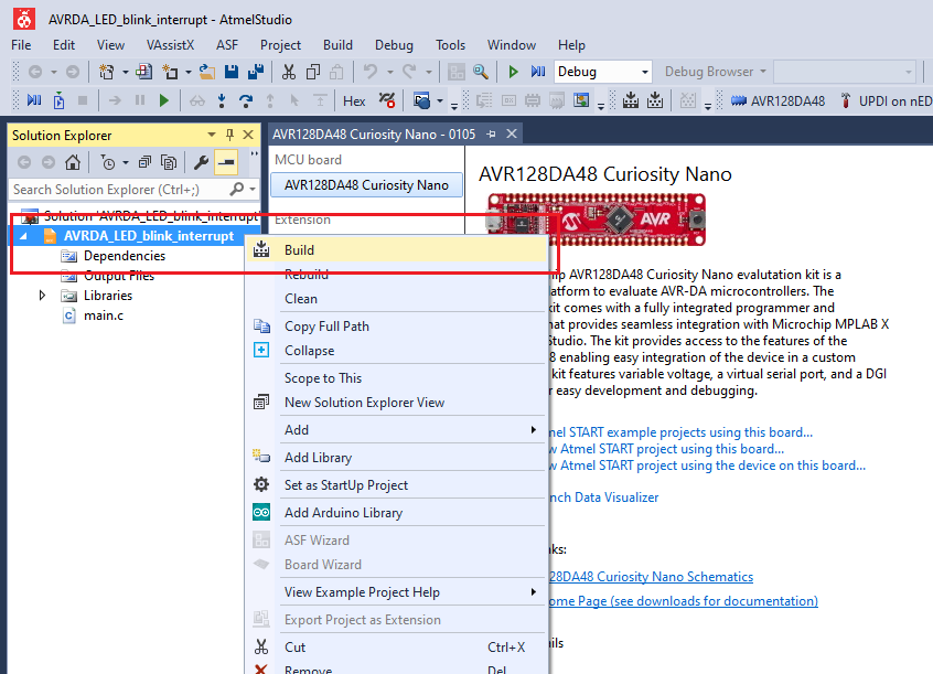
Build the solution: right click on AVRDA_LED_blink_interrupt solution and select Build
-
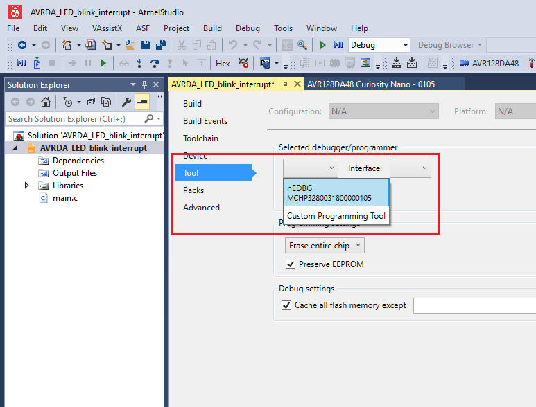
Select the AVR128DA48 Curiosity Nano on-board debugger in the Tool section of the project settings:

- Right click on the project and click Properties;
- Click Tool tab on the left panel, select the corresponding debugger and save the configuration (Ctrl + S)

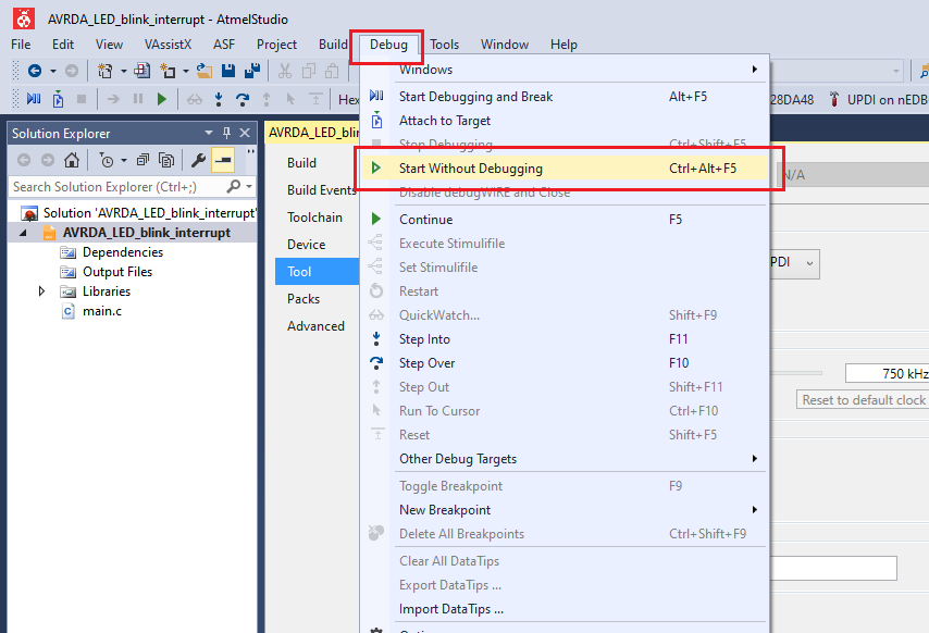
- Program the project to the board: select AVRDA_LED_blink_interrupt project and click Start Without Debugging:

Demo:

This example represents a basic LED toggling application. The toggling is implemented using the built-in delay function and the on-board LED of the AVR128DA48 Curiosity Nano is toggled every 500 milliseconds.