A lab report by Alexander Popeil
a. What color stripes are on a 100 Ohm resistor?
Answer: Brown Black Brown
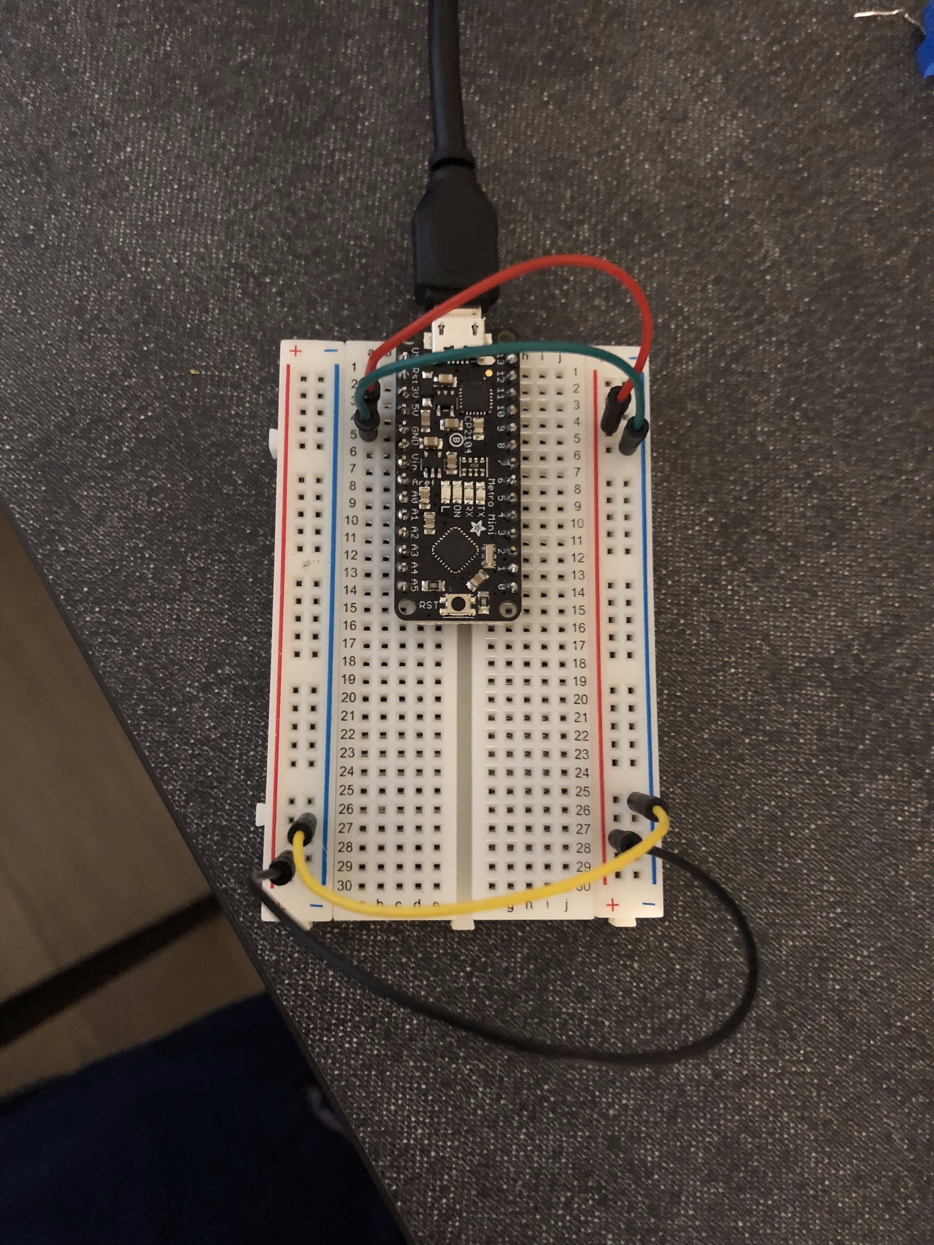
b. What do you have to do to light your LED?
Answer: When connected the LED won’t immediately light, you must press the button to connect the circuit and light the LED.
a. What line(s) of code do you need to change to make the LED blink (like, at all)?
Answer: You don’t actually need to change the example code to get the on board LED to blink, since it seems the “LED_BUILTIN” variable maps to pin 13. But if you wish you can replace “LED_BUILTIN” and get the same result.
b. What line(s) of code do you need to change to change the rate of blinking?
Answer: To change the blinking rate you only need to change the parameters of the delay() functions. This controls the pause length in-between the digitalWrites, which controls the signal outputted to the built in LED.
c. What circuit element would you want to add to protect the board and external LED?
Answer: To protect the board and external LED I would add a resistor.
d. At what delay can you no longer perceive the LED blinking? How can you prove to yourself that it is, in fact, still blinking?
Answer: I could no longer perceive the LED blinking when the delay parameter was set to 12ms. You can tell it's still blinking by using the multimeter to check the variance in voltage during the code execution.
e. Modify the code to make your LED blink your way. Save your new blink code to your lab 1 repository, with a link on the README.md.
Answer: I programmed my blinking LED to have a longer pause(5x longer) after being lit.
Make a video of your LED blinking, and add it to your lab submission.
a. Are you able to get the LED to glow the whole turning range of the potentiometer? Why or why not?
Answer: I was not able to get the LED to light through the entire range of the potentiometer. I believe this is because the voltage was too low given the resistor in the LED.
a. What do you have to modify to make the code control the circuit you've built on your breadboard?
Answer: You simply have to change the output pin to 11 in the code.
b. What is analogWrite()? How is that different than digitalWrite()?
Answer: analogWrite() sends a constant analog value to a specified pin, until analogWrite() is called again. DigitalWrite() only accepts a HIGH(5V or 3.3V) or LOW(0V) input, and outputs the corresponding voltages to declared pin. So in all, analogWrite can send a wide range of voltage values, while digitalWrite can only send a high voltage or low voltage.
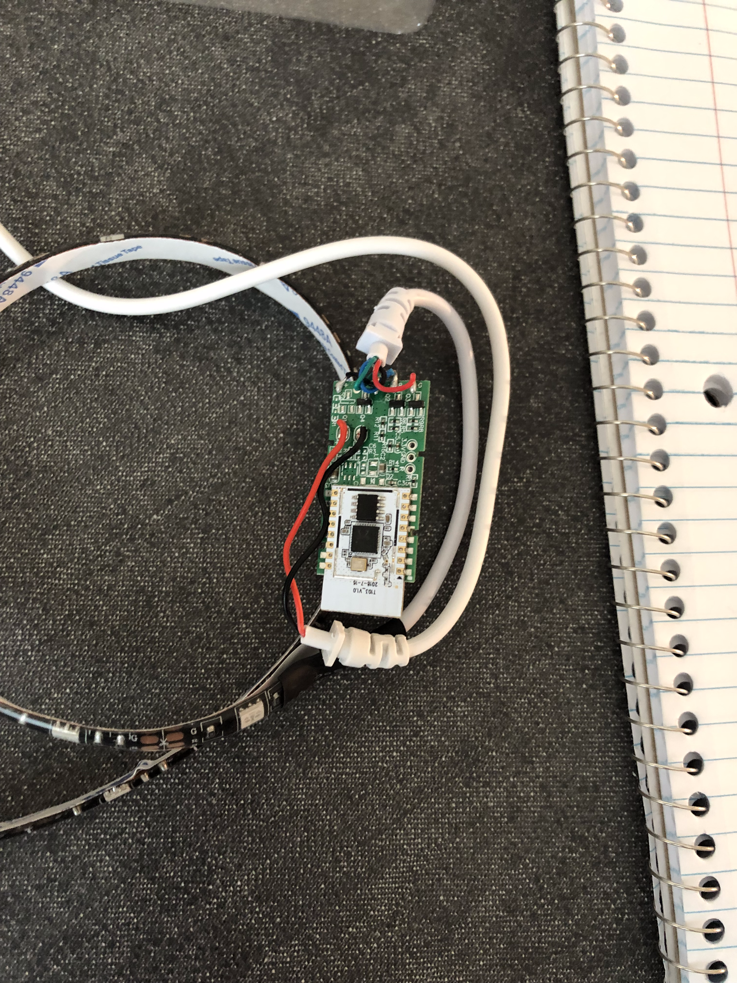
a. Is there computation in your device? Where is it? What do you think is happening inside the "computer?"
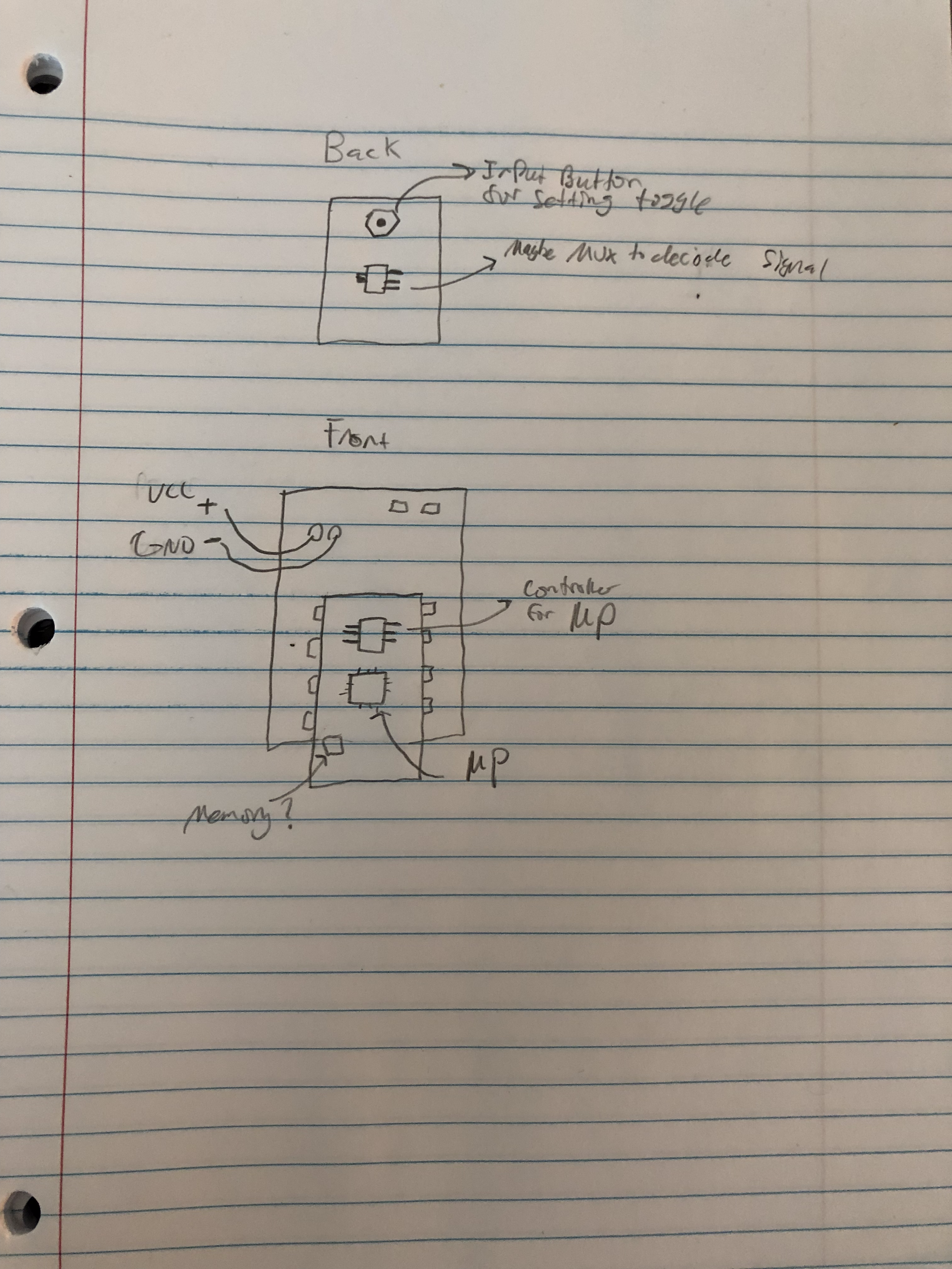
Answer: Although this device is rather simple, it can be connected to and controlled by a smartphone device. I think there is some computation being performed by a microprocessor in order to correctly set light intensity and color. Besides it’s internet capabilities, there is a physical button on the controller to toggle between two states: blinking and non-blinking. I think there is a MUX IC to decipher that signal, and an embedded ASM controller to control the microprocessor.
b. Are there sensors on your device? How do they work? How is the sensed information conveyed to other portions of the device?
Answer: I’m not really sure if there are any sensors on my device. There is a button, to control light states, but I’m not sure if that would be valid. There are probably sensors to shut the device off if it becomes overheated. If the device overheated it would probably send a signal to the ASM controller and cut power to the LEDs.
c. How is the device powered? Is there any transformation or regulation of the power? How is that done? What voltages are used throughout the system?
Answer: This device is powered through a USB port. Since the lights can be dimmed or intensified there is definitely a transformer that can send analog signals to the LED lights, based on input from the user. Just from what I’ve seen toggling between the two states, the voltages oscillate between 5.5V and 0V. If I was able to connect my smartphone, I would probably see a greater variance.
d. Is information stored in your device? Where? How?
Answer: The small chip in the bottom left corner relative to the microprocessor looks like it could be an SRAM component to store setting sent by the user through a smart device. Other than that there should be registers to store the basic toggle states controlled by the ASM, would probably be implemented as D flip flops.
2. Using your schematic, figure out where a good point would be to hijack your device and implant an LED.
I picked pins that were connecting the processing component to the rest of the board. From there I intercepted those signals and sent them to my LED light, effectively lighting it


