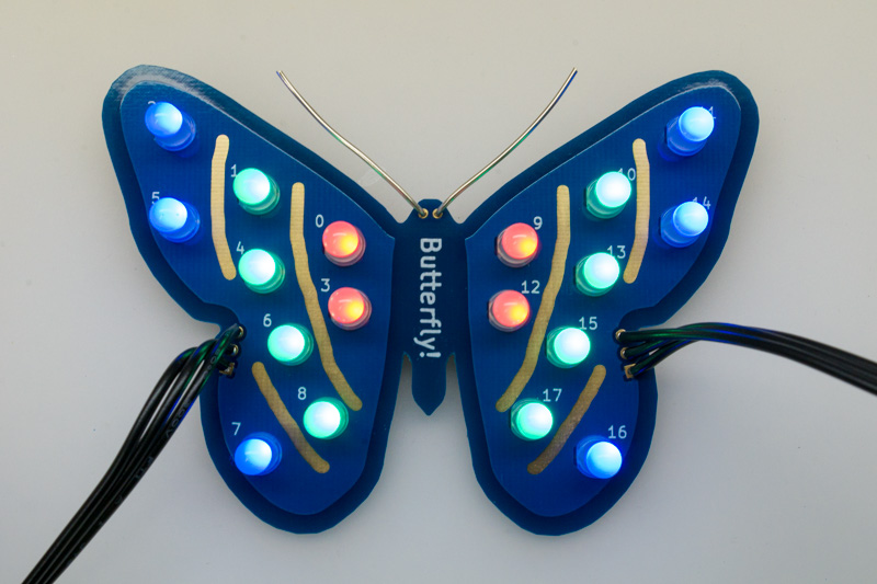
This repository contains the KiCad and Gerber files for a PCB shaped like a butterfly. The butterfly contains 18 "NeoPixel" (WS-2812) LEDs. The butterflies can be chained together, and controlled by just about any microcontroller. However, I specifically had the BBC micro:bit in mind, and designed these chainable butterflies together with my neo:bit and feather:bit boards.
The butterfly design is based on my butterfly nightlight, but I have removed the microcontroller so that it can be controlled externally.
You can use any NeoPixel library on any microcontroller to control the LEDs on the butterfly. The silkscreen shows how the LEDs are numbered. Note that the NeoPixel butterflies use RGB format, rather than the more common GRB format.
If you're using the micro:bit MakeCode editor, you can optionally use my butterfly package. It makes it easier to control the inner, middle, or outer LEDs on the butterfly as a group.
My butterfly package is not an "approved" package, so you'll need to
enter its URL specifically. Expand the "Advanced" box, and choose
"Add Package". Then enter https://github.com/ppelleti/pxt-butterfly
in the search box:
Then just choose the "butterfly" package that appears.
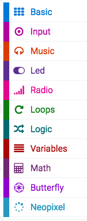
You should then have a "Butterfly" category in your toolbox:
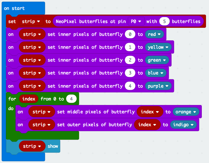
Now you can use the butterfly blocks:
Be sure to use the NeoPixel "show" block once you've set your butterfly colors.
- D1-D18 (qty 18) - 5mm through-hole NeoPixel. SparkFun part no. COM-12986. Digi-Key part no. 1568-1213-ND.
- C1 (qty 1) - 47µF 1210 capacitor. Samsung part no. CL32A476MPJNNNE. Digi-Key part no. 1276-3380-1-ND.
- J1-J2 (qty 1) - 3-pin JST SM Plug + Receptacle Cable Set. Adafruit part no. 1663.
- Bare wire, 20 AWG.
This board is big enough that it would be rather expensive to order from OSH Park, so I would recommend a Chinese fab such as Elecrow or JLCPCB. I chose blue soldermask for my boards, but red or yellow might work, as well. I chose the ENIG finish.
If you're not making any changes to the board, all you need to do is
zip up the files in the gerber directory, and upload the zipfile to
Elecrow or JLCPCB.
Note that in the KiCad files and Gerber files, the "front" of the board is actually the back, and vice-versa. This is because JLCPCB adds a customer ID number to the front of the board, but I wanted the number to be on the actual back of the board, where it doesn't disrupt the esthetics of the butterfly. (It turns out it's possible to specify the location of the customer ID, but I hadn't read that when I first came up with this trick.)
-
Solder the surface-mount capacitor C1 onto the back of the board.
-
Solder the 18 LEDs to the front of the board. The LED should be positioned so that the square pad gets one of the longer legs, not one of the shorter ones.
-
Solder the JST SM plug and receptacle to the J1 and J2 locations. Be sure to get the polarity right!
-
Create the butterfly's antennae by inserting a length of bare wire into the holes on the butterfly's head. (These two holes are represented by J3 on the schematic.) It's a tight fit, so friction may be enough to hold the wire in place, but you can always solder it to be sure.
This design is licensed under the Creative Commons Attribution-ShareAlike 4.0 International license.
Some of the footprints in myLibrary.pretty are based on footprints
in the KiCad library, which is licensed under the
KiCad library license (which is now also CC-BY-SA-4.0, with an
exception).


