Parallel EEPROM Programmer for SST29EE020 (and possibly others which use 128 byte pages, the protocol for programming EEPROMs is standard) featuring:
- GUI-based front-end written in Python
- Ability to program memories up to 1 MB in size with the current pin configuration, theoretically up to 4 GB possible (although good luck with the 500 Kbps transfer rate)
- Possibility to access the programmer via a serial monitor
- Hardware UART with 500 Kbps for data transfer to/from PC via USB
- Utilizing the fast page write mode of the EEPROM
- Binary data transmission
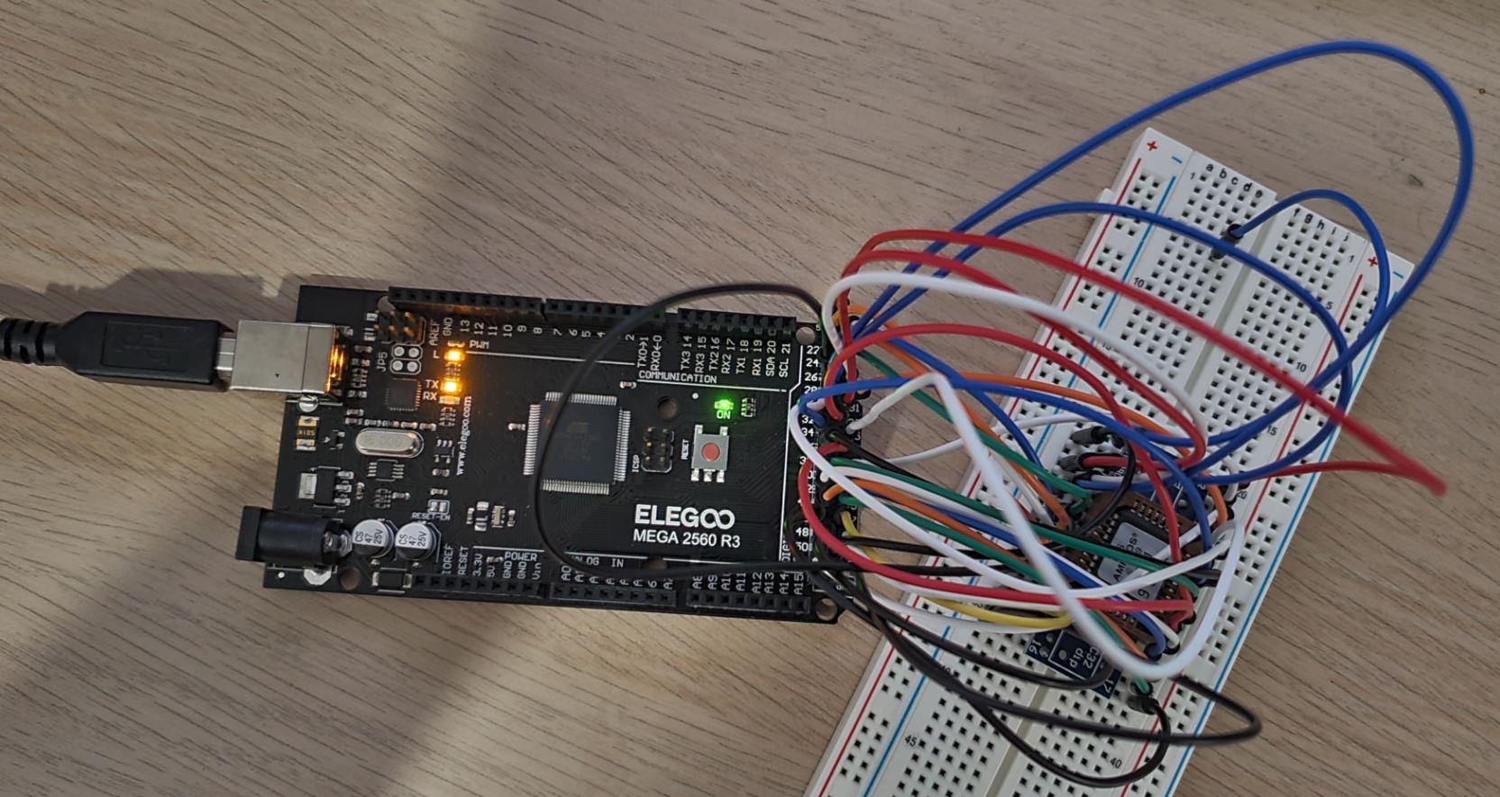
The heart of the EEPROM programmer is an ATmega2560 microcontroller. The address bus of the EEPROM (up to 20 bit in the current configuration, with modifications 32 bits are possible) as well as the data bus is controlled directly via the pins of the ATmega. The data connection to the PC runs via the hardware UART interface of the ATmega transfering the data in binary format with up to 500 Kbps.
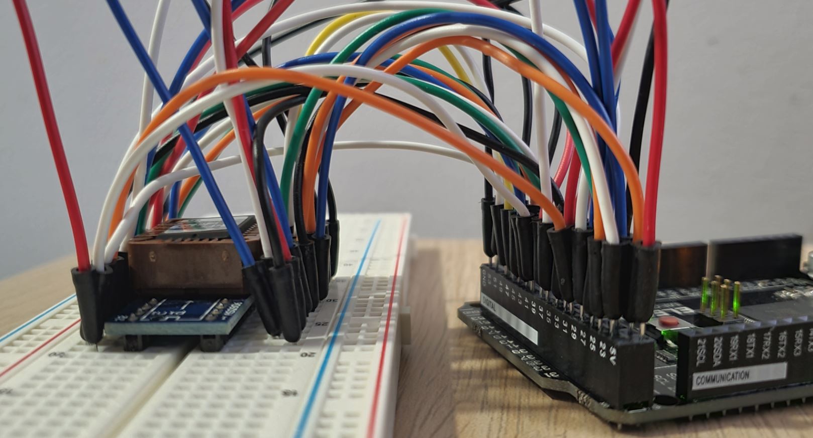
SST29EE020 to ATmega2560 connections are shown in below table (ATmega2560 Pinout). A simple PLCC32 to DIP32 adapter board (See example under section 12) can be used with a PLCC32 EEPROM. Such adapter with model number "ASQ906" is used here, which is cheaply avaialble from AliExpress. These would have 1-to-1 pin mapping from PLCC32 to DIP32. Please recheck the pin mapping of your adapter before connecting EEPROM as there could be some adapters with different pin mapping from PLCC32 to DIP32.
| Chip Pin | Description | Arduino PIN | Description |
|---|---|---|---|
| 1 | NC | N/A | N/A |
| 2 | A16 | Digital pin 53 | PB0 |
| 3 | A15 | Digital pin 30 | PC7 |
| 4 | A12 | Digital pin 33 | PC4 |
| 5 | A7 | Digital pin 29 | PA7 |
| 6 | A6 | Digital pin 28 | PA6 |
| 7 | A5 | Digital pin 27 | PA5 |
| 8 | A4 | Digital pin 26 | PA4 |
| 9 | A3 | Digital pin 25 | PA3 |
| 10 | A2 | Digital pin 24 | PA2 |
| 11 | A1 | Digital pin 23 | PA1 |
| 12 | A0 | Digital pin 22 | PA0 |
| 13 | DQ0 | Digital pin 49 | PL0 |
| 14 | DQ1 | Digital pin 48 | PL1 |
| 15 | DQ2 | Digital pin 47 | PL2 |
| 16 | VSS | GND | GROUND |
| 17 | DQ3 | Digital pin 46 | PL3 |
| 18 | DQ4 | Digital pin 45 | PL4 |
| 19 | DQ5 | Digital pin 44 | PL5 |
| 20 | DQ6 | Digital pin 43 | PL6 |
| 21 | DQ7 | Digital pin 42 | PL7 |
| 22 | CE# | Digital pin 39 | PG2 |
| 23 | A10 | Digital pin 35 | PC2 |
| 24 | OE# | Digital pin 40 | PG1 |
| 25 | A11 | Digital pin 34 | PC3 |
| 26 | A9 | Digital pin 36 | PC1 |
| 27 | A8 | Digital pin 37 | PC0 |
| 28 | A13 | Digital pin 32 | PC5 |
| 29 | A14 | Digital pin 31 | PC6 |
| 30 | A17 | Digital pin 52 | PB1 |
| 31 | WE# | Digital pin 41 | PG0 |
| 32 | VCC | 5V | 5V |
On the microcontroller side, data is received via UART and written to the EEPROM according to the data sheet or vice versa. The programmer is controlled with simple commands, which are also sent via the serial interface:
| Command | Function |
|---|---|
| i | Print "EEPROM Programmer" (for identification) |
| v | Print firmware version |
| a 00000100 | Set address bus to 00000100 (hex) (for test purposes) |
| d 00000000 0003ffff | Print hex dump of memory addresses 0000000-0003ffff (hex) = 256 KiB |
| f 00001000 00001fff ff | Fill memory (00001000-00001fff) with value ff (hex) |
| r 00000000 0003ffff | Read memory addresses 0000000-0003ffff (hex) and send as binary data |
| p 00000100 0000017f | Page write binary data to memory page 00000100-0000017f (bytes must follow) |
| l | Lock EEPROM (enable write protection) |
| u | Unlock EEPROM (disable write protection) |
| e | Perform chip erase |
Any serial monitor (set BAUD rate to 500000) can be used for control from the PC. However, in order to use the full capabilities, it is recommended to use the attached Python scripts.
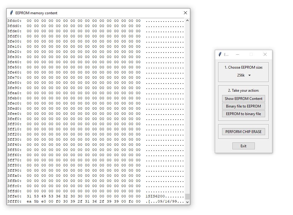
The script "eepromgui.py" offers a simple graphical user interface and functions for reading and writing binary files as well as for displaying the EEPROM content.
- Go to Tools -> Board -> Arduino AVR Boards and select Arduino Mega or Mega 2560.
- Go to Tools -> Processor and select ATmega2560 (Mega 2560).
- Connect your Arduino Mega to your PC.
- Open "EEPROM_Programmer_m2560.ino" sketch in the "software" folder and click Upload.
- Create new anaconda enviornment and install necessary libraries
conda create -n eeprom python=3.9
conda activate eeprom
pip install pyserial
- Check whether USB-to-Serial PID/VID is correct at
eeprom.py, change it according to your Arduino. Belows shows the default value for Arduino Mega with ATMEL USB-to-Serial chip.
        pid = '2341'
        hid = '0042'
- Run GUI "eepromgui.py" (screenshot shown below). Don't forget to activate correct anaconda environment with
conda activate eeprombefore running.
python eepromgui.py
- After programming, read the content of the EEPROM and save it as a binary file. Then, use a HEX comparision tool (like Beyond Compare) to verify the content of the chip before using it on another circuit.
This work is licensed under Creative Commons Attribution-ShareAlike 3.0 Unported License. (http://creativecommons.org/licenses/by-sa/3.0/)


