NOTE: This library is not being actively developed (but reported bugs will still be fixed). Development is continuing in Rust (with a C FFI), the repository is here.
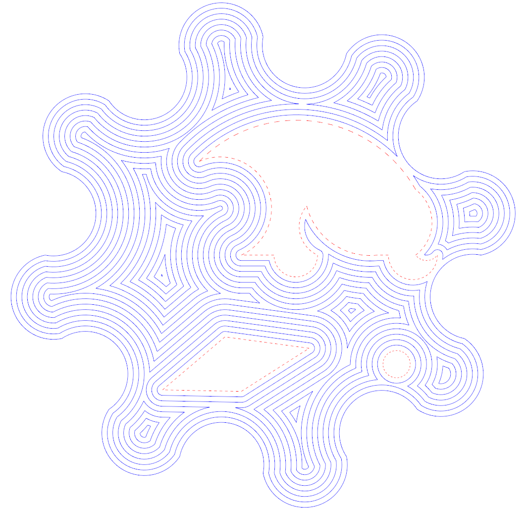
C++14 header only library (with a C API available) for processing 2D polylines containing both straight line and constant radius arc segments. Supports contour/parallel offsetting, boolean operations (OR, AND, NOT, XOR) between closed polylines, and other common functions (winding number, area, path length, distance to point, etc.). For interactive UI and development go to the development project CavalierContoursDev. For quick code examples look in the examples. Live web demo available here (note the page is quite large and may take a minute to download, it's created by building the CavalierContoursDev project to web assembly using Emscripten). For the C API header look here.
- Summary
- Table of Contents
- Quick Code Example
- Polyline Structure
- Other Programming Languages
- Offset Algorithm and Stepwise Example
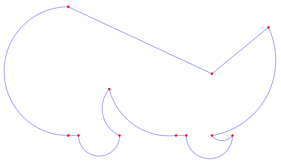
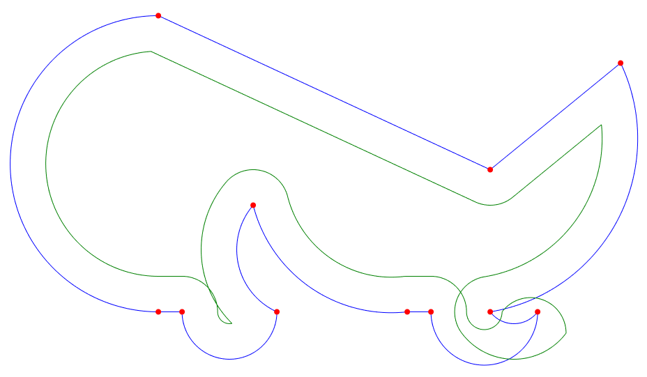
- Original input polyline, pline in blue, vertexes in red
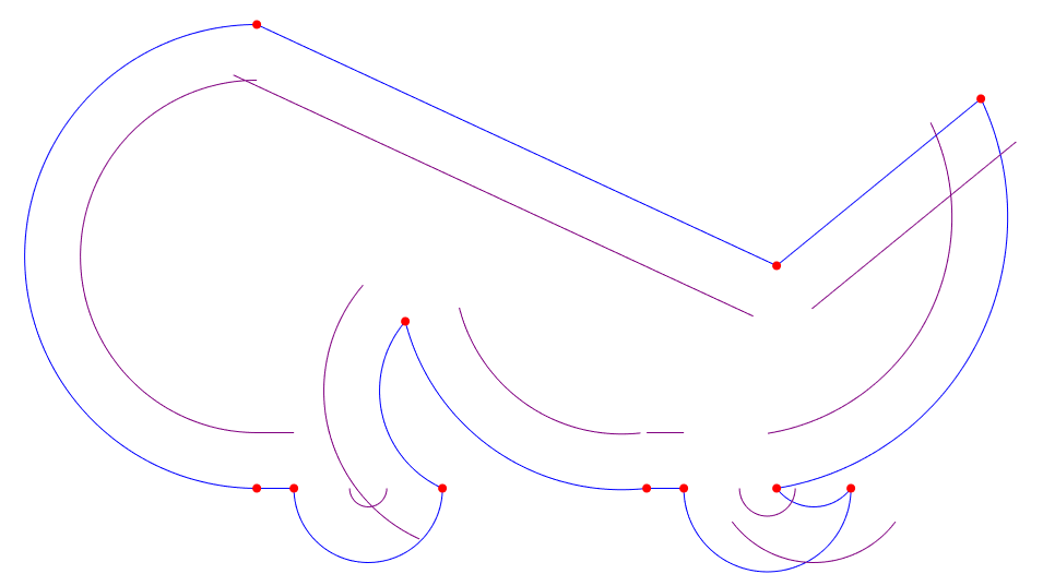
- Raw offset segments generated in purple (Step 1)
- Raw offset polyline created from raw offset segments, pline1 (in green) (Step 2)
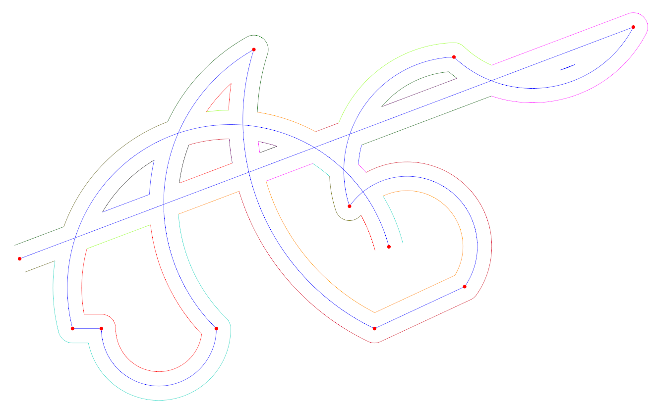
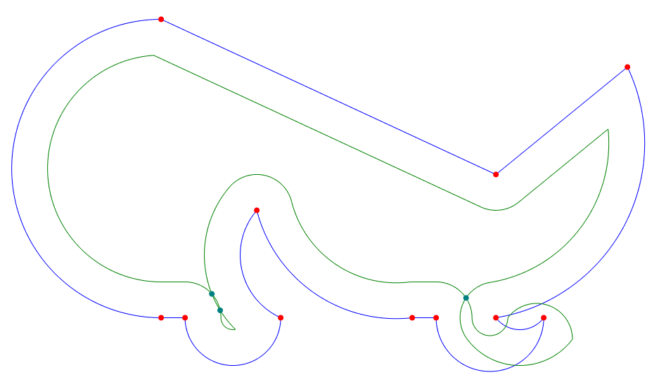
- Raw offset polyline self intersects (dark cyan) (Step 4)
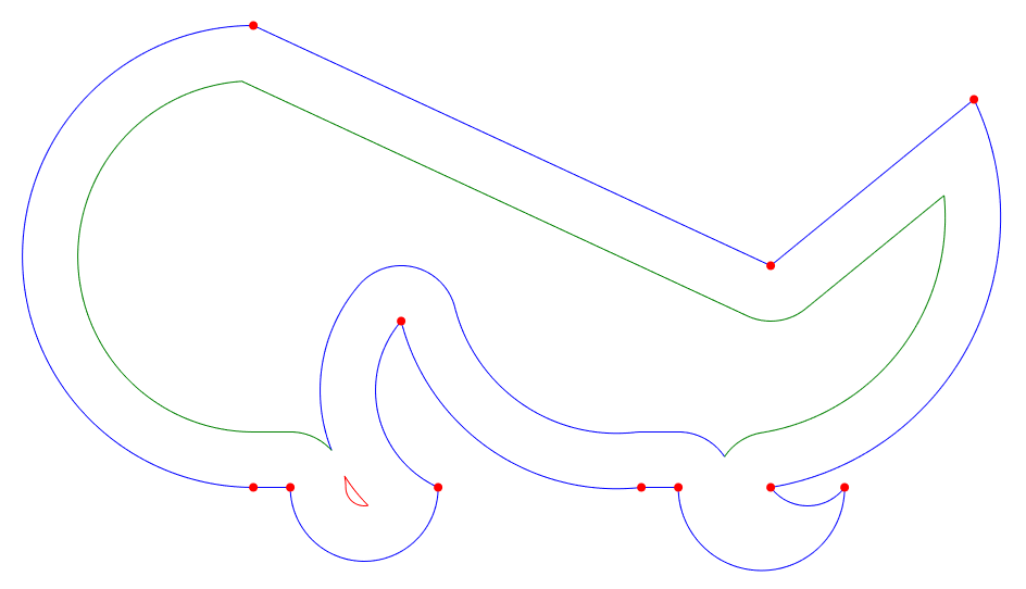
- Valid open polyline slices created from self intersects (in green, red, and blue) (Step 5 & 6)
- Open polyline slices stitched together (in red and blue) (Step 7)
- Interactively Exploring the Algorithm
- Performance
- Implementation Notes and Variations
- Development
- API Stability
- Project Motivation and Goal
- Algorithm Complexity and 2D Spatial Indexing
- References
#include "cavc/polylineoffset.hpp"

// input polyline
cavc::Polyline<double> input;
// add vertexes as (x, y, bulge)
input.addVertex(0, 25, 1);
input.addVertex(0, 0, 0);
input.addVertex(2, 0, 1);
input.addVertex(10, 0, -0.5);
input.addVertex(8, 9, 0.374794619217547);
input.addVertex(21, 0, 0);
input.addVertex(23, 0, 1);
input.addVertex(32, 0, -0.5);
input.addVertex(28, 0, 0.5);
input.addVertex(39, 21, 0);
input.addVertex(28, 12, 0);
input.isClosed() = true;

// compute the resulting offset polylines, offset = 3
std::vector<cavc::Polyline<double>> results = cavc::parallelOffset(input, 3.0);
NOTE: If the offset results are wrong in some way you may need to adjust the scale of the numbers, e.g. scale the inputs up by 1000 (by multiplying all the X and Y components of the vertexes by 1000), perform the offset (with the offset value also scaled up by 1000), and then scale the output result back down by 1000. This is due the fixed bit representation of floating point numbers and the absolute float comparing and thresholding used by the algorithm.
Polylines are defined by a sequence of vertexes and a bool indicating whether the polyline is closed or open. Each vertex has a 2D position (x and y) as well as a bulge value. Bulge is used to define arcs, where bulge = tan(theta/4). theta is the arc sweep angle from the starting vertex position to the next vertex position. If the polyline is closed then the last vertex connects to the first vertex, otherwise it does not (and the last vertex bulge value is unused). See [2] for more details regarding bulge calculations.
CavalierContours is written in C++ and makes available a C API. Here are some wrappers in other languages:
Python (wraps the C API)
- Generate raw offset segments from the input polyline, pline.
- Create the raw offset polyline, pline1, by trimming/joining raw offset segments acquired in step 1.
- If the input polyline, pline, has self intersections or is an open polyline then repeat steps 1 and 2 with the offset negated (e.g. if the offset was 0.5 then create raw offset polyline with offset of -0.5), this is known as pline2.
- Find all self-intersects of pline1. If step 3 was performed then also find all intersects between pline1 and pline2. If pline is an open polyline then also find intersects between pline1 and circles at the start and end vertex points of pline with radius equal to the offset.
- Create a set of open polylines by slicing pline1 at all of the intersect points found in step 4.
- Discard all open polyline slices whose minimum distance to pline is less than the offset.
- Stitch together the remaining open polyline slices found in step 6, closing the final stitched results if pline is closed.
The algorithm is mostly based on Liu et al. [1] with some differences since the algorithm they describe for GCPP (general closest point pair) clipping fails for certain inputs with large offsets (or at least I am unable to make their algorithm work).
The key clarifications/differences are:
- When raw offset segments are extended to form a raw offset polyline they are always joined by an arc to form a rounded constant distance from the input polyline.
- Dual offset clipping is only applied if input polyline is open or has self intersects, it is not required for a closed polyline with no self intersects.
- If the polyline is open then a circle is formed at each end point with radius equal to the offset, the intersects between those circles and the raw offset polyline are included when forming slices.
- GCPP (general closest point pair) clipping is never performed and instead slices are formed from intersects, then they are discarded if too close to the original polyline, and finally stitched back together.
- No special handling is done for adjacent segments that overlap (it is not required given the slice and stitch method).
- Collapsing arc segments (arcs whose radius is less than the offset value) are converted into a line and specially marked for joining purposes.
Here is example code and visualizations of the algorithm operating on a closed polyline with no self intersects as input.
An interactive UI app (implemented using Qt and QML) is available (CavalierContoursDev) to visualize and explore in real time the offset algorithm. This app is also compiled to web assembly, for the live web version go here. The app was used to generate all the images in this markdown.
The implementation is not entirely geared around performance but some profiling has been done to determine where to reserve memory up front and avoid trig functions where possible. I suspect there is quite a bit of performance to be gained in using a custom memory allocator, and there may be ways to modify the algorithm to prune invalid segments faster.
Additionally the structures and control flow are factored for readability/maintainability and may be limiting how much is compiled to simd instructions.
The following is a series of benchmarks that were run on windows 10 64 bit with an i7 6700k @ 4.00Ghz, code was built using MSVC 2019 compiler version 19.24.28314 targeting 64 bit (similar results were found using MingGW 7.3 64 bit). Each benchmark profile has different characteristics, and each profile is repeatedly offset both inward and outward with increasing delta.
All offsets were performed with rounded joins (maintaining exact offset distance from original input), and 1e8 was used to scale the double inputs into 64 bit integers for input into the Clipper library (but scaling and copying is not included in the benchmarks to avoid penalizing Clipper). Offsets are always computed from the original input (not from previous offset results) to avoid the explosion of vertexes from rounded joins approximated by line segments created by Clipper.
- BM_square is a simple square with 4 edges.
- BM_circle is a simple circle defined by two vertexes with bulge = 1 (half circle arcs).
- BM_roundedRectangle is a rectangle with corner radii.
- BM_Profile1 is a small closed polygon with 4 arcs and 2 line segments.
- BM_Profile2 is a slightly larger closed polygon with 7 arcs and 4 line segments.
- BM_PathologicalProfile1/N is a circle whose perimeter is composed of half circle arcs alternating clockwise and counter clockwise. N is the number of half circles that make up the perimeter. This is a pathological input for 2d bounding box spatial indexing: as the offset delta increases all of the raw offset segment's bounding boxes start to overlap, and all of the segments start to intersect.
1e-2 (0.01) and 1e-3 (0.001) at the end of "arcs approx." refers to the error when approximating an arc as a series of line segments, it is the maximum allowed distance between the approximating line segments and the original arc. Note the profile vertex distances are in the range of 0-50 so the 1e-2 (0.01) error is intolerable for many applications, but significantly cuts down on the number of generated segments.
| benchmark | vertex count | arcs approx. 1e-2 vertex count | arcs approx. 1e-3 vertex count |
|---|---|---|---|
| BM_square | 4 | 4 | 4 |
| BM_circle | 2 | 142 | 446 |
| BM_roundedRectangle | 8 | 56 | 164 |
| BM_Profile1 | 6 | 80 | 241 |
| BM_Profile2 | 11 | 162 | 494 |
| BM_PathologicalProfile1/10 | 10 | 400 | 1240 |
| BM_PathologicalProfile1/25 | 25 | 625 | 1975 |
| BM_PathologicalProfile1/50 | 50 | 900 | 2800 |
| BM_PathologicalProfile1/100 | 100 | 1300 | 4000 |
All times are wall time. Exact details of the benchmark profiles and offsets run can be found under the dev project here. For more on the clipper library see [11].
| benchmark | cavc arcs approx. 1e-2 (ms) | clipper arcs approx. 1e-2 (ms) | cavc vs. clipper |
|---|---|---|---|
| BM_square | 0.21 | 0.72 | 3.5x |
| BM_circle | 9.11 | 9.47 | 1.0x |
| BM_roundedRectangle | 3.92 | 8.46 | 2.2x |
| BM_Profile1 | 8.55 | 6.33 | 0.7x |
| BM_Profile2 | 17.57 | 16.59 | 0.9x |
| BM_PathologicalProfile1/10 | 34.97 | 136.46 | 3.9x |
| BM_PathologicalProfile1/25 | 70.93 | 241.95 | 3.4x |
| BM_PathologicalProfile1/50 | 138.17 | 514.95 | 3.7x |
| BM_PathologicalProfile1/100 | 336.37 | 1347.09 | 4.0x |
| benchmark | cavc arcs approx. 1e-3 (ms) | clipper arcs approx. 1e-3 (ms) | cavc vs. clipper |
|---|---|---|---|
| BM_square | 0.21 | 1.71 | 8.1x |
| BM_circle | 38.04 | 61.37 | 1.6x |
| BM_roundedRectangle | 13.14 | 61.61 | 4.7x |
| BM_Profile1 | 27.07 | 24.44 | 0.9x |
| BM_Profile2 | 52.64 | 73.64 | 1.4x |
| BM_PathologicalProfile1/10 | 109.96 | 1383.46 | 12.6x |
| BM_PathologicalProfile1/25 | 227.51 | 2824.67 | 12.4x |
| BM_PathologicalProfile1/50 | 385.46 | 6170.26 | 16.0x |
| BM_PathologicalProfile1/100 | 821.15 | 15797.60 | 19.2x |
The above benchmarks were taken by converting all arcs to line segments before running the profile through the offsetting algorithm. Even with no arcs in the input CavalierContours is competitive with a noticeable speedup in many cases. This is in part due to CavalierContours not having to construct rounded joins from line segments (an exact arc can be constructed instead).
| benchmark | cavc w/ arcs (ms) | clipper arcs approx. 1e-2 (ms) | cavc vs. clipper |
|---|---|---|---|
| BM_square | 0.21 | 0.72 | 3.4x |
| BM_circle | 0.12 | 9.47 | 76.4x |
| BM_roundedRectangle | 0.49 | 8.46 | 17.3x |
| BM_Profile1 | 0.76 | 6.33 | 8.4x |
| BM_Profile2 | 1.55 | 16.59 | 10.7x |
| BM_PathologicalProfile1/10 | 1.61 | 136.46 | 84.9x |
| BM_PathologicalProfile1/25 | 7.17 | 241.95 | 33.8x |
| BM_PathologicalProfile1/50 | 23.98 | 514.95 | 21.5x |
| BM_PathologicalProfile1/100 | 85.10 | 1347.09 | 15.8x |
| benchmark | cavc w/ arcs (ms) | clipper arcs approx. 1e-3 (ms) | cavc vs. clipper |
|---|---|---|---|
| BM_square | 0.21 | 1.71 | 8.1x |
| BM_circle | 0.12 | 61.37 | 494.7x |
| BM_roundedRectangle | 0.49 | 61.61 | 126.1x |
| BM_Profile1 | 0.76 | 24.44 | 32.3x |
| BM_Profile2 | 1.55 | 73.64 | 47.6x |
| BM_PathologicalProfile1/10 | 1.61 | 1383.46 | 861.0x |
| BM_PathologicalProfile1/25 | 7.17 | 2824.67 | 394.2x |
| BM_PathologicalProfile1/50 | 23.98 | 6170.26 | 257.3x |
| BM_PathologicalProfile1/100 | 85.10 | 15797.60 | 185.6x |
The above benchmarks compare CavalierContours taking in the original input (arcs included) vs. Clipper (arcs must be approximated). The performance benefits of processing the arcs directly is quickly realized.
When comparing two float values for equality, a and b, this implementation uses a simple fuzzy comparing method of abs(a - b) < epsilon, where epsilon is a very small number, e.g. 1e-8 or 1e-5 depending on the context. These numbers were picked through anecdotal use case trial/error where input values are typically between 0.1 and 1000.0. If finer comparisons are required, or if the input values get quite large or small then numerical stability issues may arise and the means of fuzzy comparing will need to be adjusted. See mathutils.hpp for c++ implementation.
When joining raw offset segments together the current implementation always uses an arc to connect adjacent segments if they do not intersect, the arc maintains a constant distance from the original input polyline. Alternatively these joins could be done by extending the original line/arc segments until they intersect or by some other means entirely. Note that any other type of join will result in the offset polyline not being at a constant offset distance from the original input.
When stitching the open polylines together the current implementation only looks to stitch end points to start points. This assumes that the slices will always stitch together this way, this is a valid assumption if all slices are from the same raw offset polyline, but in the case that you want to stitch slices from different offsets together the implementation must look at both start and end points since directionality may change.
When stitching open polylines together the current implementation attempts to stitch the slices into the longest polylines possible (there are multiple possibilities when slices become coincident or tangent at end points with one another). Alternatively one could implement it in a way to stich slices into the shortest polylines possible. This may be useful if in the case of coincident stretches the result should be marked or discarded.
Pull requests, feature requests/ideas, issues, and bug reports are welcome. Please attempt to follow the code style and apply clang-format (using the .clang-format file) before making a pull request.
There is not an official release yet - all functions and structures are subject to change. This repository for now serves as an implementation reference that is easy to understand and possibly transcribe to other programming languages. The code can be used as is, but there is no guarantee that future development will maintain the same functions and structures. Ideas/pull requests for what a stable API interface should look like are welcome.
Tentatively the C API is stable, see header file here, but has not yet been solidified in a 1.0 release.
I set out to generate tool compensated milling tool paths for profile cuts, in the process I found many papers on offsetting curves for CAD/CAM uses [1][9][10][16], but there is often no reference implementation. Most algorithms described are dense and difficult to reproduce. Issues such as numeric stability, how to handle coincident segments, process collapsing arcs, etc. are often not mentioned, and the algorithmic description detail is inconsistent. It may be very clear how to perform some of the steps, but other steps are quickly glossed over, and it becomes unclear how to go about implementing. All of these issues would not be much of a problem if an open source reference implementation was supplied, but for all the papers I have read not a single implementation was given.
In addition to papers being difficult to utilize as a pragmatic tool, most papers focus on offsetting straight segment polylines or polygons (sometimes referred to as point sequence curves) [9][10][16]. And there are a few notable open source libraries that work only on straight segment polylines as well [11][12][13]. Unfortunately if only straight segments are supported then all curves, even simple constant radius arcs, must be approximated using straight segments. This leads to an inefficient memory footprint, and additional algorithmic steps if arcs must be reconstructed from points after offsetting. Constant radius arcs are very common in CAD/CAM applications (tool compensation, tool offsetting for cleanout, part sizing, etc.), and arcs may be used to approximate other types of curves more memory efficiently than straight line segments, e.g. for Bezier curves [14].
There are a few papers on offsetting curves with arc segments [1][15], some involve a Voronoi diagram approach [15], and others are more similar to the approach this library takes by processing self-intersects and applying a clipping algorithm [1]. These papers do not provide an opensource reference implementation, and many of them are difficult to understand, and even more difficult to reproduce.
The goal of this project is to provide a simple, direct, and pragmatic algorithm and reference implementation for polyline offsetting (supporting both lines and arcs, open and closed) for use in CAD/CAM applications. It includes the minimum computational geometry building blocks required (vectors, spatial indexing, etc.) to accomplish this goal. The code is written with the intent that it can be easily read, modified, and transcribed to other programming languages. The interactive UI app can be used to help understand the algorithm visually and make parts of the code easier to digest.
The algorithm requires finding self-intersects, testing the distance between points and the original polyline, testing for intersects between new segments and the original polyline, and stitching open polylines together end to end. The naïve approach to such steps typically results in O(n2) algorithmic complexity where each segment must be tested against every other segment and each point must be tested against every segment.
The approach used by this library is to use a packed Hilbert R-Tree [3]. See staticspatialindex.hpp for c++ implementation. See [4] and [5] for more implementation references. This results in an algorithm complexity of O(n log n) for typical inputs, with worse case O(n2) for pathological inputs.
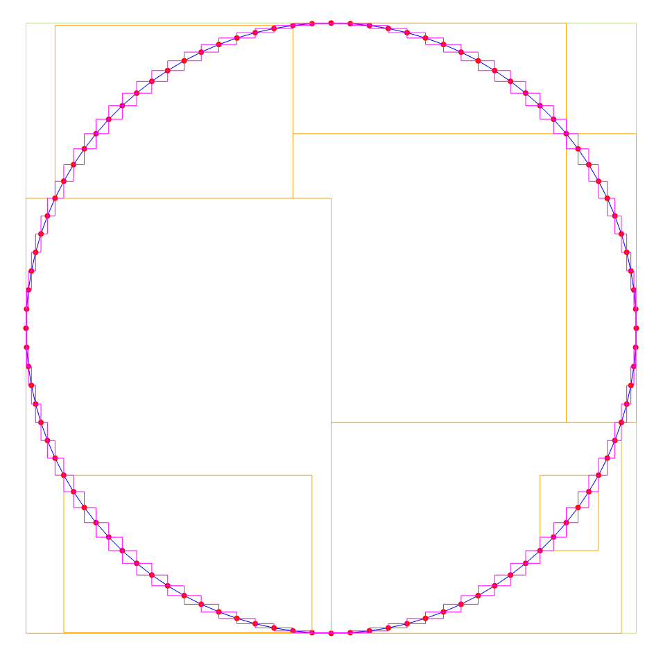
Here is an image of a closed polyline approximating a circle using 100 line segments (blue lines and red vertexes) with spatial index bounding boxes made visible (magenta, orange, and light green boxes). The root of the R-Tree is the light green box, its children are the orange boxes, and its grand children are the magenta boxes.
The packed Hilbert R-Tree is very fast to build and query, but requires rebuilding the tree anytime the data changes – however for computational geometry algorithms such as those performed in this library we start with no indexed data, and our data does not change for the duration of the algorithm, making the tradeoff ideal for the use case.
There are alternative approaches, e.g. by combining an Interval Tree [6] and binary heap [7] a sweep line algorithm [8] approach can be taken to avoid O(n2) complexity.
Note that there are pathological input cases that will still result in O(n2) behavior even with a spatial index or sweep line algorithm. E.g. a polyline for which all segments have axis-aligned bounding boxes that overlap. But for common inputs seen in CAD/CAM applications this is not the case, and a run time complexity of O(n log n) will result.
[1] Liu, X.-Z., Yong, J.-H., Zheng, G.-Q., & Sun, J.-G. (2007). An offset algorithm for polyline curves. Computers in Industry, 58(3), 240–254. doi:10.1016/j.compind.2006.06.002
[2] Bulge conversions: http://www.lee-mac.com/bulgeconversion.html
[3] https://en.wikipedia.org/wiki/Hilbert_R-tree#Packed_Hilbert_R-trees
[4] JavaScript spatial index implementation: https://github.com/mourner/flatbush/
[5] Fast 2D to 1D Hilbert curve mapping used for spatial index: https://github.com/rawrunprotected/hilbert_curves
[6] https://en.wikipedia.org/wiki/Interval_tree
[7] https://en.wikipedia.org/wiki/Binary_heap
[8] https://en.wikipedia.org/wiki/Sweep_line_algorithm
[9] Lin, Z., Fu, J., He, Y., & Gan, W. (2013). A robust 2D point-sequence curve offset algorithm with multiple islands for contour-parallel tool path. Computer-Aided Design, 45(3), 657–670. doi:10.1016/j.cad.2012.09.002
[10] Kim, D.-S. (1998). Polygon offsetting using a Voronoi diagram and two stacks. Computer-Aided Design, 30(14), 1069–1076. doi:10.1016/s0010-4485(98)00063-3
[11] Clipper library: http://www.angusj.com/delphi/clipper.php (github fork here: https://github.com/jbuckmccready/clipper-lib)
[12] CGAL library for offsetting polylines: https://doc.cgal.org/latest/Straight_skeleton_2/index.html
[13] Boost geometry: https://www.boost.org/doc/libs/1_53_0/libs/geometry/doc/html/index.html
[14] Bezier biarc approximating: https://github.com/domoszlai/bezier2biarc
[15] Held, M., & Huber, S. (2009). Topology-oriented incremental computation of Voronoi diagrams of circular arcs and straight-line segments. Computer-Aided Design, 41(5), 327–338. doi:10.1016/j.cad.2008.08.004
[16] Kim, H.-C., Lee, S.-G., & Yang, M.-Y. (2005). A new offset algorithm for closed 2D lines with Islands. The International Journal of Advanced Manufacturing Technology, 29(11-12), 1169–1177. doi:10.1007/s00170-005-0013-1


