AWR1843BOOST fields 'range', 'doppler_bin', 'bearing' and 'intensity' are always zero
Claud1234 opened this issue · 15 comments
I save the '.cfg' file from the online demo visualizer and load it into ROS pipeline. There are no values for fields 'range', 'doppler_bin', 'bearing' and 'intensity' in any default scenes (best range, best range resolution, best velocity resolution) whatever it is 2d or 3d. But I can get the velocity values all the time.
You have to check the files DataHandlerClass.cpp and mmWave.h
In DataHandlerClass.cpp you can recognize that in the command READ_OBJ_STRUCT no information about range, doppler_bin, bearing and intensity is saved for SDK verisons older than 3.x. Intensity and noise are saved in the command READ_SIDE_INFO. A better understanding of how the data is managed for SDK 3.x can be found in the file mmWave.h.
There is only one .msg file and that is RadarScan.msg. Probably this .msg file was done for SDK versions older than 3.x and nobody changed it since then. I also saw that there is still work in progress for AWR1843 devices.
Currently, I am also doing a project with an AWR1843 radar but I am not an expert and this is what I could figure out until now.
Hi @alme96
I think your point about the changes of SDK 3.x makes sense. I did a close look of source codes of the SDK 3.x and current 'DataHandlerClass.cpp', it is true that the 'intensity' and 'range' works in a different way for new version SDK.
In my opinion, 'range' information in Cartesian Coordinate can be calculated by (x,y,z) values. There is spherical coordinate structure in SDK 3.x, it has the 'range' information, but things works different in spherical coordinate.
It is true that the 'intensity' was saved in 'SIDE_INFO', and you can read its information directly. But take care the unit of the values you read from the 'SIDE_INFO', the unit of values is dB, so no need to do logarithmic calculation anymore, but I think you have to divide the SNR values in 'SIDE_INFO' by 10, because it is said the unit of that is 0.1dB in SDK.
Currently, I can not see a use of 'doppler_bin' and 'bearing' information in my project, so I did not look at it too much. In original 'DataHandlerClass.cpp' code, you can see these two fields are calculated by existing information. I think you can choose to include these two fields for SDK 3.x if you need.
I did some modifications of the original code. I added the missing information in 'RadarScan' topic. There are also 'range' and 'velocity' fields published in PointCloud2 topic in addition to 'intensity'. Here is the link:
https://github.com/Claud1234/ti_mmwave_rospkg
There might be issues of the code. Feel free to modify and comment it.
Regards
Claude
Hi @Claud1234
Thank you a lot for your help!
Where did you find the definitions to extract the spherical coordinates from the SDK?
I managed to display the spherical and the cartesian coordinates but I had some issues:
- If I use the function memcpy on range, azimuth, elevation and velocity, the sensor seems to crash after having started with the following message:
terminate called after throwing an instance of 'std::out_of_range'
what(): vector::_M_range_check: __n (which is 3424) >= this->size() (which is 3424)
[ti_mmwave-2] process has died [pid 18453, exit code -6, cmd /home/menichea/catkin_ws/devel/lib/ti_mmwave_rospkg/ti_mmwave_rospkg __name:=ti_mmwave __log:=/home/menichea/.ros/log/be75f338-0fcb-11eb-a351-e4a7a0ae757c/ti_mmwave-2.log].
log file: /home/menichea/.ros/log/be75f338-0fcb-11eb-a351-e4a7a0ae757c/ti_mmwave-2.log*
I cannot really understand the error as I have no idea to which vector is referred in the error. - The spherical coordinates do not coincide with the cartesian coordinates. I could confirm the cartesian values by measuring the real distances from the radar. I am pretty sure that the spherical values are wrong as I have also got negative radial value, and if I compute the azimuth and the elevation angle from the cartesian values I do not get a similar value.
Did you encounter these problems too while trying to read the spherical values?
Best Regards
Ale
Hi @alme96
Where did you find the definitions to extract the spherical coordinates from the SDK?
You can find the header file about spherical and Cartesian coordinate in /package/ti/datapath/dpif/, but things in it are similar to the 'mmWave.h' in this repository.
-
I remembered I caught the same error as you showed. I did not check how the function 'memcpy' exactly works, but my problem is I mixed the information from 'DPIF_PointCloudSideInfo_t' and 'DPIF_PointCloudSpherical_t' into the same structure to publish. for example, I took the x,y,z from 'DPIF_PointCloudSideInfo_t' and 'range' from 'DPIF_PointCloudSpherical_t' then publish them together (soon I realized the 'range' in spherical is a different thing). Maybe the 'std::out_of_range' error is because of this. I recommend you look at the details of function 'memcpy' if you really have a use of spherical coordinate.
-
In /package/ti/datapath/dpif/src, there is an example about the conversion between spherical and Cartesian coordinate. I am not really understand why you are so sure spherical coordinate is wrong. I did not use spherical coordinate too much in my stuffs.
I am pretty sure that the spherical values are wrong as I have also got negative radial value, and if I compute the azimuth and the elevation angle from the cartesian values I do not get a similar value.
Refer to SDK, in spherical coordinate, negative azimuthAngle means left hand side, negative elevAngle means below the sensor. I do not know what is your sensor configuration and the details of your problem, you might have to check these things over again.
Maybe try to convert the spherical to Cartesian to check whether it is correct?
Hope my opinions can help you in some ways.
All the best,
Claude
Hi @Claud1234
Thank you for your time! At the end I won't use spherical coordinates either but it was helpful to understand how the radar works.
Best regards,
Ale
I save the '.cfg' file from the online demo visualizer and load it into ROS pipeline. There are no values for fields 'range', 'doppler_bin', 'bearing' and 'intensity' in any default scenes (best range, best range resolution, best velocity resolution) whatever it is 2d or 3d. But I can get the velocity values all the time.
Hello, I also try to use AWR1843BOOST with this ROS package to collect point cloud data. But I am not good at using ROS so far, so I wonder if you are kind to share some instructions about how to use this code repository, such as how to capture the message and write it into a txt file, and how to start and terminate the data collection. Thanks a lot!
Hi @Carbord ,
- take a look at the file DataHandlerClass.cpp
- the data is extracted with the memcpy function (you can look it up)
- the values are written on the ti_mmwave_rospkg/RadarScan message type, which is a costumized message type
- take a look at all the .h files where everything is defined
- read the discussion that Claud and I had carefully
I hope these hints can help you starting your project, I am also new to ROS and C++ so I do not want to give you hints that could be misleading and wrong.
King regards,
Ale
Hi @Carbord:
I wonder if you are kind to share some instructions about how to use this code repository<<
The README written by original author explained the usage of the repository very detailed. All you need to do is pick up the configuration files which you want. In your case, if the sensor is AWR1843BOOST, the configuration files should based on this specific model. You can do as @alme96, try to connect the sensor to online visualizer, then tune and save the .cfg files as you need. Otherwise, please check the my fork repository, there are .cfg files I saved as default modes 'best_range_resolution' 'best_velocity_resolution' 'best_range' in both 2D and 3D for AWR1843BOOST sensor. If you have problems to read the README, I suggest you read more about ROS basic functions first, this definitely will help you.
how to capture the message and write it into a txt file<<
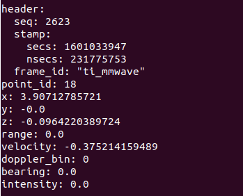
If you can connect the sensor and run the node successfully, you can have two topics about the output of the sensor. One is a customized message which is like the screenshot I shared in this page. This topic indicate the object detection information. Another topic is regular ROS PointCloud2 topic which shows all the points sensor captured. It is also possible to convert the ROS topics to text files if you need so, although the static files used to be very large. There should be a lot of open source packages available to do this job even for customized message.
how to start and terminate the data collection<<
I am not really understand what you mean about this question. If the sensor connection to PC is okay and node is running without error, sensor will publish all topics constantly, you can choose to record or do other post-processes with these topics simultaneously. You kill the rosnode, it will stop the data publication. The point of ROS package is to have a friendly interface to control the sensor.
I hope my answer can help you in some ways.
Regards
Claude
Hi @Carbord:
I wonder if you are kind to share some instructions about how to use this code repository<<
The README written by original author explained the usage of the repository very detailed. All you need to do is pick up the configuration files which you want. In your case, if the sensor is AWR1843BOOST, the configuration files should based on this specific model. You can do as @alme96, try to connect the sensor to online visualizer, then tune and save the .cfg files as you need. Otherwise, please check the my fork repository, there are .cfg files I saved as default modes 'best_range_resolution' 'best_velocity_resolution' 'best_range' in both 2D and 3D for AWR1843BOOST sensor. If you have problems to read the README, I suggest you read more about ROS basic functions first, this definitely will help you.
how to capture the message and write it into a txt file<<
If you can connect the sensor and run the node successfully, you can have two topics about the output of the sensor. One is a customized message which is like the screenshot I shared in this page. This topic indicate the object detection information. Another topic is regular ROS PointCloud2 topic which shows all the points sensor captured. It is also possible to convert the ROS topics to text files if you need so, although the static files used to be very large. There should be a lot of open source packages available to do this job even for customized message.
how to start and terminate the data collection<<
I am not really understand what you mean about this question. If the sensor connection to PC is okay and node is running without error, sensor will publish all topics constantly, you can choose to record or do other post-processes with these topics simultaneously. You kill the rosnode, it will stop the data publication. The point of ROS package is to have a friendly interface to control the sensor.
I hope my answer can help you in some ways.
Regards
Claude
Thanks a lot! I will try and learn.
Hi @Carbord ,
If you have not red the radar user guide and the mmwave-sdk user guide yet, I suggest that you start with those, so that you understand, for example, how to flash your device.
Good luck with your project!
Ale
I save the '.cfg' file from the online demo visualizer and load it into ROS pipeline. There are no values for fields 'range', 'doppler_bin', 'bearing' and 'intensity' in any default scenes (best range, best range resolution, best velocity resolution) whatever it is 2d or 3d. But I can get the velocity values all the time.
That's because the DataHandlerClass.cpp seems to have those messages commented out:

Please uncomment those lines, rebuild the project and try again. It should work. Let me know if this problem persists.
uncommentating them doesn't help while building package it shows error it wont help us much i think and its in else case if the particular fields of data not present it show think so we need to look for the data we get out of the radar and map it accordingly if any one can guide we can try it
Maybe you can change the code in DataHandlerClass.cpp like below. After I changed it like this, it worked. If the problem persists, feel free to contact me.
Remember to comment the codes related to radar_scan_pub.publish(radarscan) in "case READ_OBJ_STRUCT:".
case READ_SIDE_INFO:
// Make sure we already received and parsed detected
// obj list (READ_OBJ_STRUCT)
if (mmwData.numObjOut > 0)
{
for (i = 0; i < mmwData.numObjOut; i++)
{
//get snr (unit is 0.1 steps of dB)
memcpy( &mmwData.sideInfo.snr,
¤tBufp->at(currentDatap),
sizeof(mmwData.sideInfo.snr));
currentDatap += ( sizeof(mmwData.sideInfo.snr) );
//get noise (unit is 0.1 steps of dB)
memcpy( &mmwData.sideInfo.noise,
¤tBufp->at(currentDatap),
sizeof(mmwData.sideInfo.noise));
currentDatap += ( sizeof(mmwData.sideInfo.noise) );
// Use snr for "intensity" field
// (divide by 10 since unit of snr is 0.1dB)
RScan->points[i].intensity = mmwData.sideInfo.snr / 10.0;
/////////////////////////////////////////////////////////////////added by me
radarscan.header.frame_id = frameID;
radarscan.header.stamp = ros::Time::now();
radarscan.point_id = i;
radarscan.x = RScan->points[i].x;
radarscan.y = RScan->points[i].y;
radarscan.z = RScan->points[i].z;
radarscan.range = RScan->points[i].range;
radarscan.velocity = RScan->points[i].velocity;
radarscan.doppler_bin = RScan->points[i].doppler_bin;
radarscan.bearing = RScan->points[i].bearing;
radarscan.intensity = RScan->points[i].intensity;
if (((maxElevationAngleRatioSquared == -1) ||
(((RScan->points[i].z * RScan->points[i].z) /
(RScan->points[i].x * RScan->points[i].x +
RScan->points[i].y * RScan->points[i].y)
) < maxElevationAngleRatioSquared)
) &&
((maxAzimuthAngleRatio == -1) ||
(fabs(RScan->points[i].y /
RScan->points[i].x) < maxAzimuthAngleRatio)) &&
(RScan->points[i].x != 0)
)
{
radar_scan_pub.publish(radarscan);
}
/////////////////////////////////////////////////////////////////////////////////////////
}
}
else // else just skip side info section if we have not already
// received and parsed detected obj list
{
i = 0;
while (i++ < tlvLen - 1)
{
//ROS_INFO("DataUARTHandler Sort Thread :
// Parsing Side Info i=%d and tlvLen = %u", i, tlvLen);
}
currentDatap += tlvLen;
}
sorterState = CHECK_TLV_TYPE;
break;
Member
hello
i added the code you wrote but i still have some problems with the
radarscan.doppler_bin = RScan->points[i].doppler_bin;
radarscan.bearing = RScan->points[i].bearing;
radarscan.intensity = RScan->points[i].intensity;
actually the error says that the struct mmwavecloudtype has no member named bearing
Member
hello
i added the code you wrote but i still have some problems with the radarscan.doppler_bin = RScan->points[i].doppler_bin; radarscan.bearing = RScan->points[i].bearing; radarscan.intensity = RScan->points[i].intensity; actually the error says that the struct mmwavecloudtype has no member named bearing
Sorry for that. May you can clone my new repo from here for working with AWR1843 device.