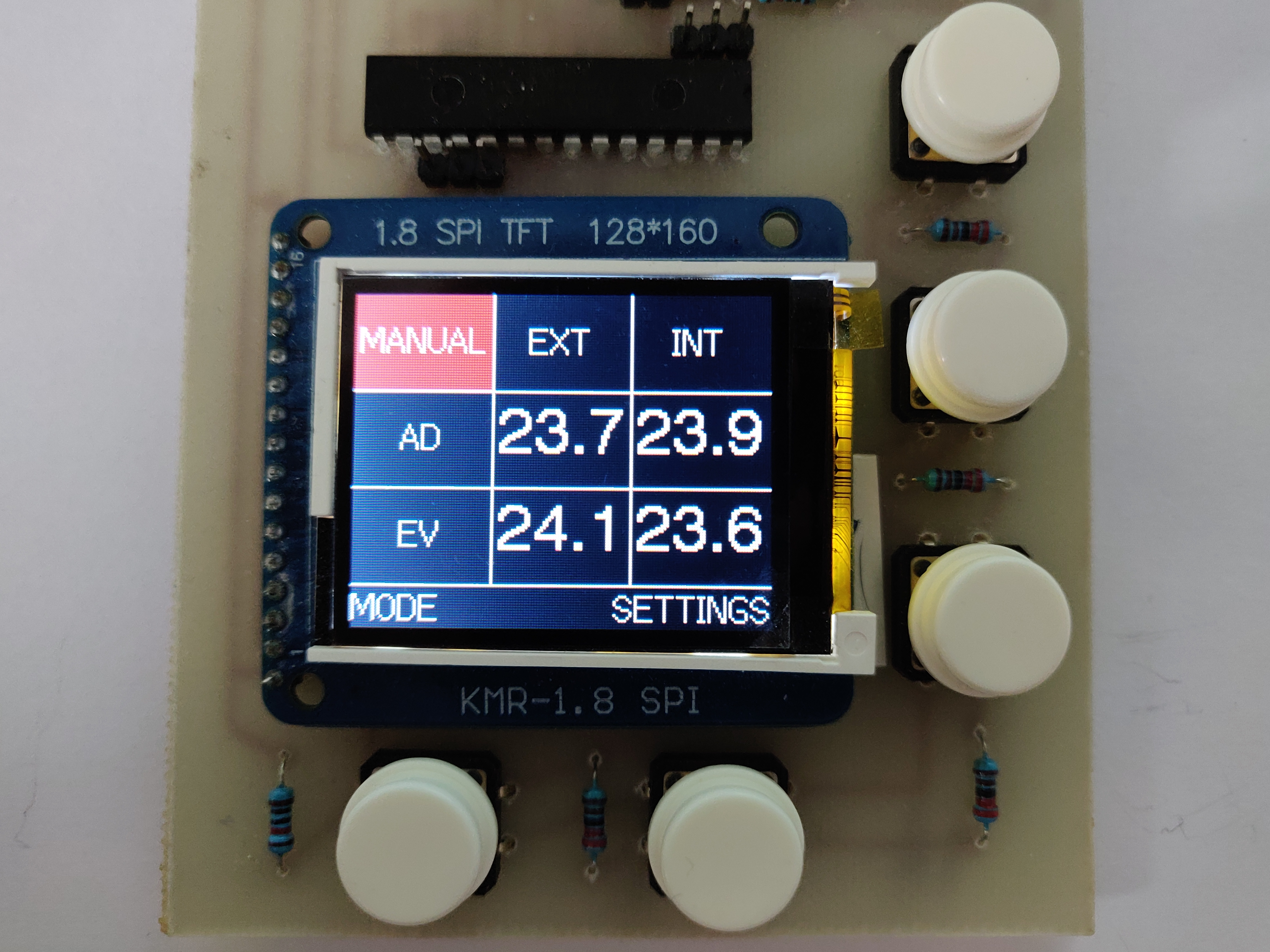
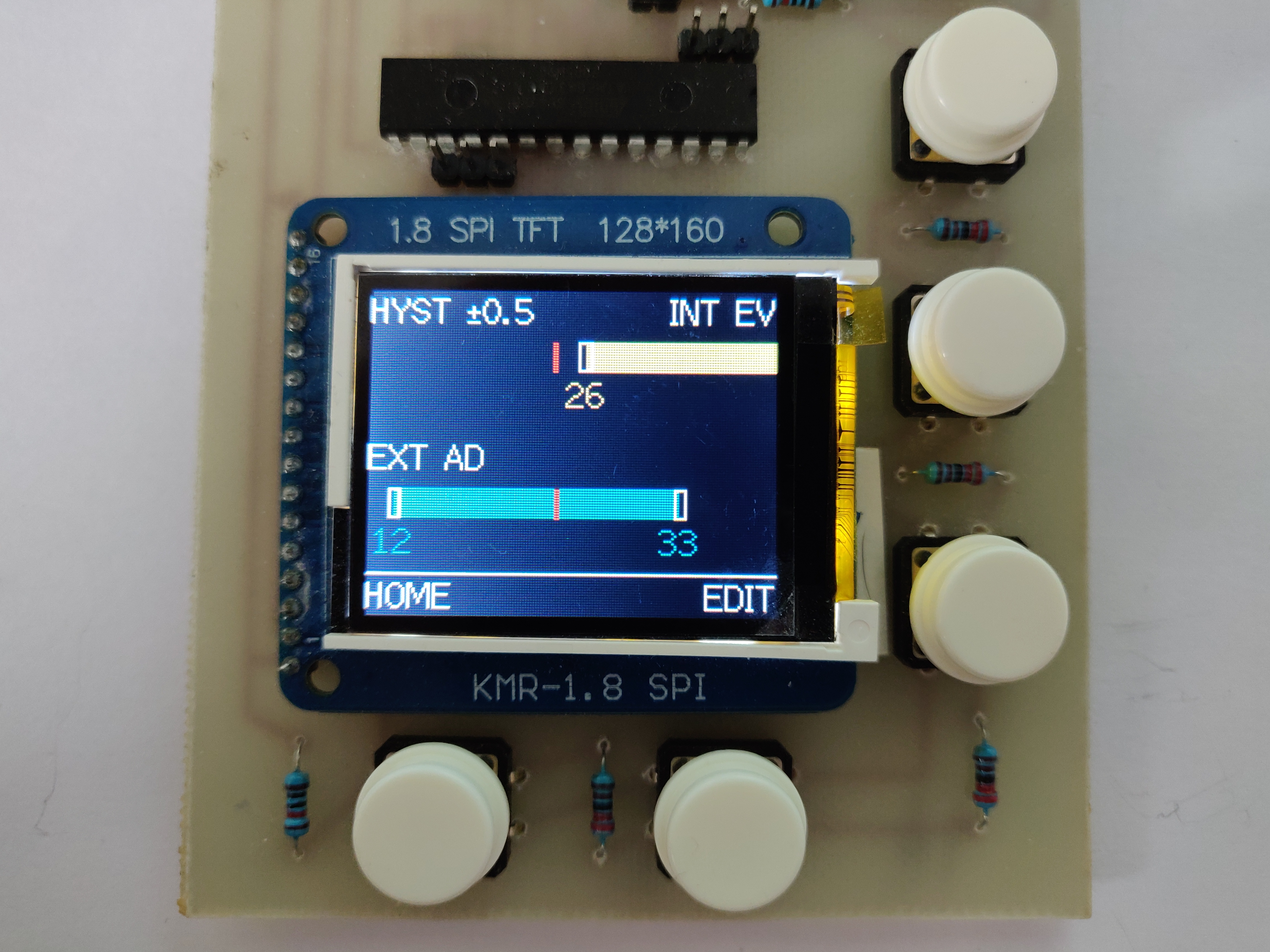
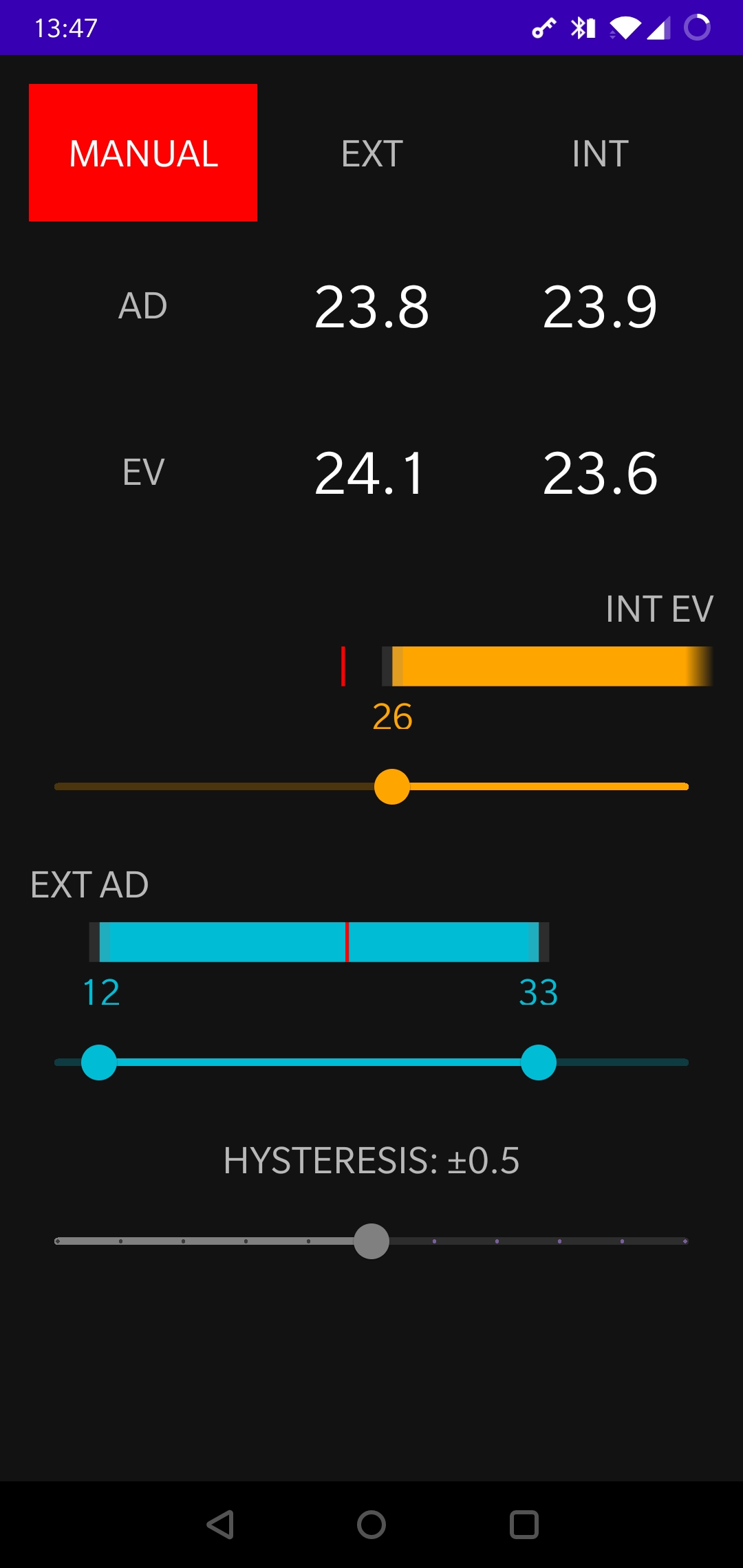
IOT device able to control the MVHR Summer Bypass based on inside and outside temperatures.
Both the mvhr-bypass-arduino and the mvhr-bypass-esp8266 projects can be edited and compiled with VSCode, which needs the Arduino IDE installed and the following VSCode plugins:
Check the release notes for each MVHR Bypass repo for the latest dependency versions known to work with that specific release.
In addition, the mvhr-bypass-arduino project relies on the TFT_ILI9163 library, which is included as a git submodule.
The mvhr-bypass-common repository contains code which is shared by both mvhr-bypass-arduino and mvhr-bypass-esp8266 and is included in those repos as a git submodule.
Add a new entry every time a new version is released. New releases go on top.
| mvhr-bypass-arduino | TFT_ILI9163 | mvhr-bypass-esp8266 | mvhr-bypass-common | mvhr-bypass-android |
|---|---|---|---|---|
| 1.0.0 | 1.0.0 | 1.0.0 | 1.0.0 | 1.0.0 |
Available options:
-
Using an Arduino board as an ISP:
-
Write the ArduinoISP sketch which is included with Arduino IDE (located in File -> Examples -> ArduinoISP)
-
Hook up the Arduino Uno to the ATmega328p (Double check the sketch in case these change in future versions):
Arduino Uno Pin ATmega328p Pin D10 RST D11 D11 D12 D12 D13 D13 - In VSCode, select the Arduino as ISP programmer and then run the Arduino: Upload Using Programmer command.
-
Available options:
-
OTA Update:
- Have the PC connected to the same network as ESP8266
- In VSCode, in
arduino.json, set theportvalue to the current IP address of the ESP8266 - Upload
-
Direct Serial Flashing:
-
On the Arduino board, hook up the RST pin to GND (this bypasses the onboard microcontroller so you can use just the built in USB to Serial functionality)
-
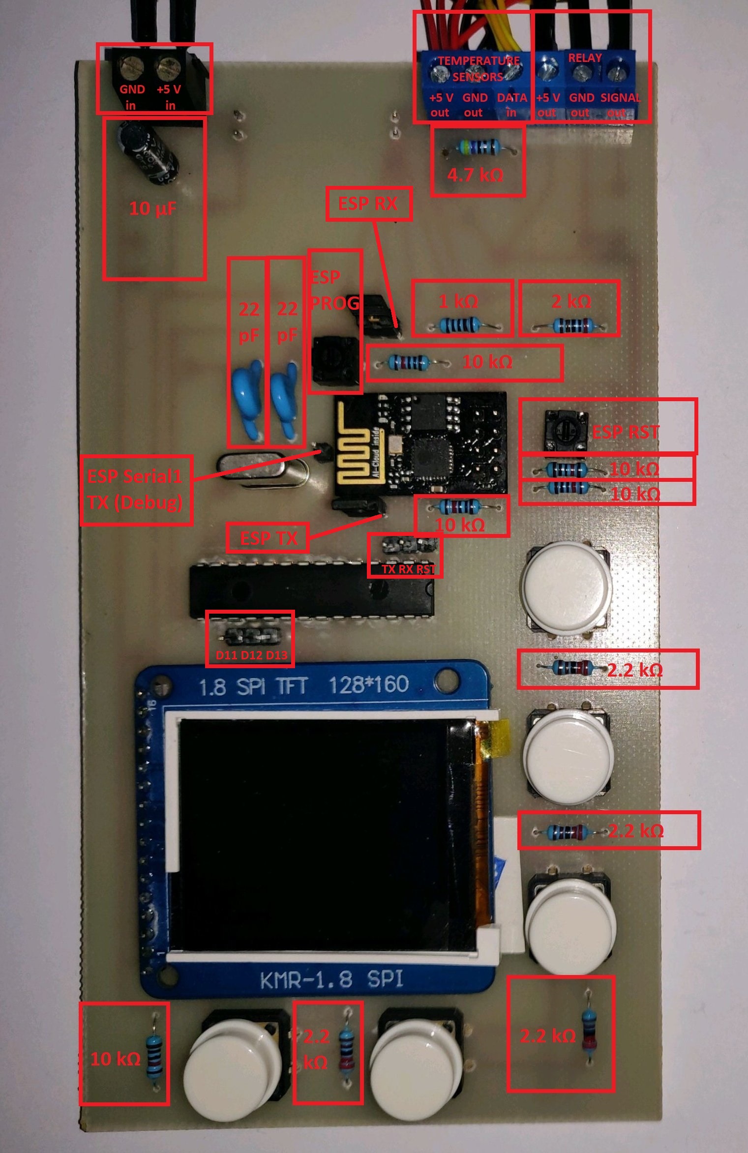
Remove the two header jumpers that allow the ESP8266 and the ATmega328p to communicate through serial
-
Hook up the Arduino board to the ESP8266:
Arduino Pin ESP8266 Pin RX RX (through the voltage divider) TX TX -
Get the ESP8266 in Program Mode:
- Press and hold the ESP RST micro-switch
- Press and hold the ESP PROG micro-switch
- Release the ESP RST micro-switch
- Release the ESP PROG micro-switch
-
In VSCode, select the appropriate Serial port
-
Upload
-
Press the ESP RST micro-switch to reset to normal mode
-
-
On the Arduino board, hook up the RST pin to GND
-
For the ATmega328p, hook up:
Arduino Pin ATmega328p Pin TX TX -
For the ESP8266, hook up:
Arduino Pin ESP8266 Pin TX Serial1 TX -
Open the Serial Monitor and set the baud rate to 9600 bps
- 1x 2 pin screw connector
- 1x 6 pin screw connector (or 2x 3 pin)
- 1x AMS1117 module (3.3 V)
- 1x 10 µF capacitor
- 1x ATmega328P-PU
- 2x 22 pF capacitors
- 1x 16 MHz crystal
- 1x ESP8266-01 (labeled "AI-Cloud inside")
- 5x push buttons (4 pin)
- 2x micro-switches (2 pin)
- 2x header jumpers (2 pin)
- 11x header pins
- 1x ILI9163 1.8" SPI TFT 128*160 (labeled "KMR-1.8 SPI")
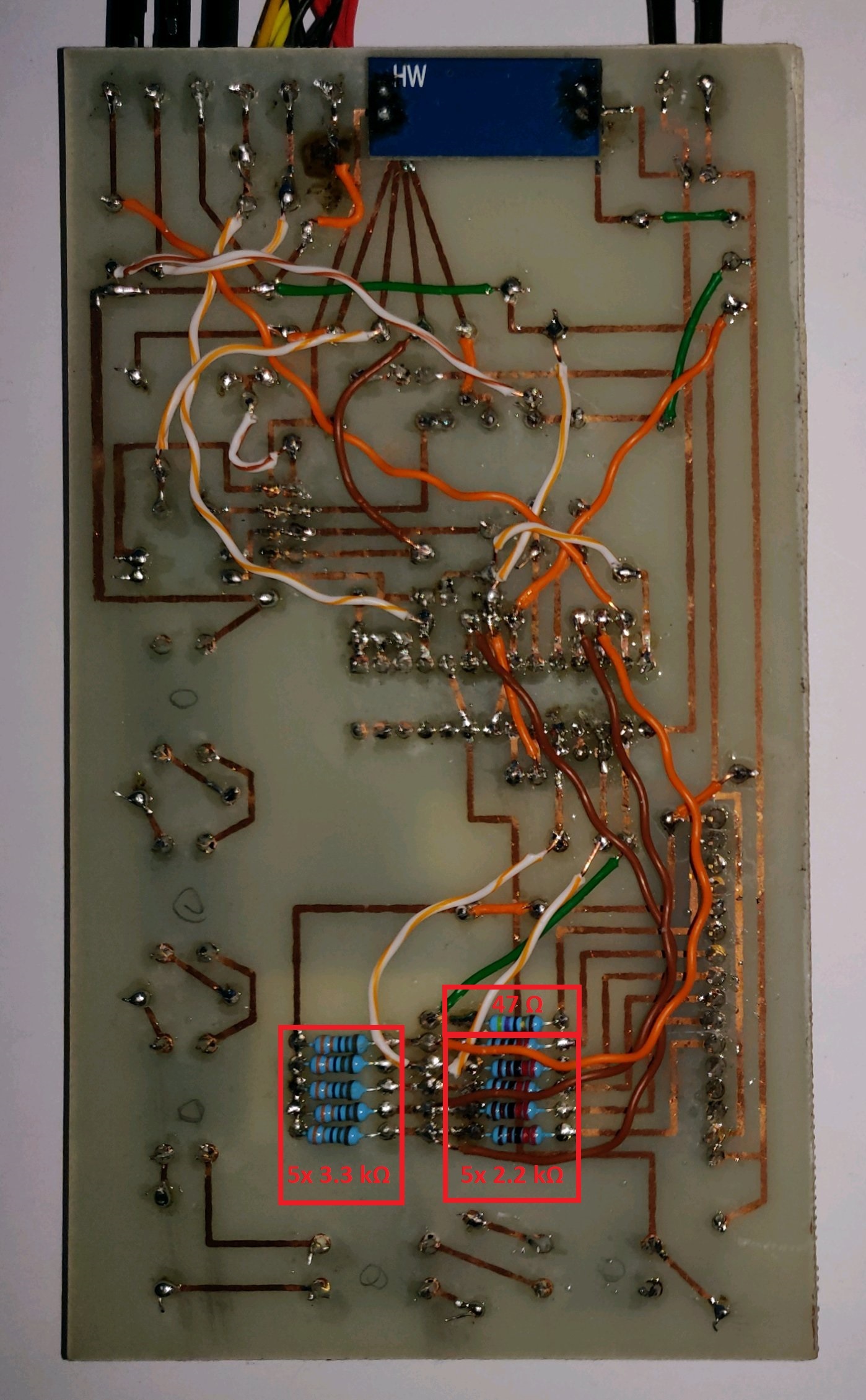
- 1x 47 Ω resistor
- 1x 1 kΩ resistor
- 1x 2 kΩ resistor
- 9x 2.2 kΩ resistor
- 5x 3.3 kΩ resistor
- 1x 4.7 kΩ resistor
- 5x 10 kΩ resistor
- 1x Relay (5 V)
- 4x DS18B20 Temperature sensors
