
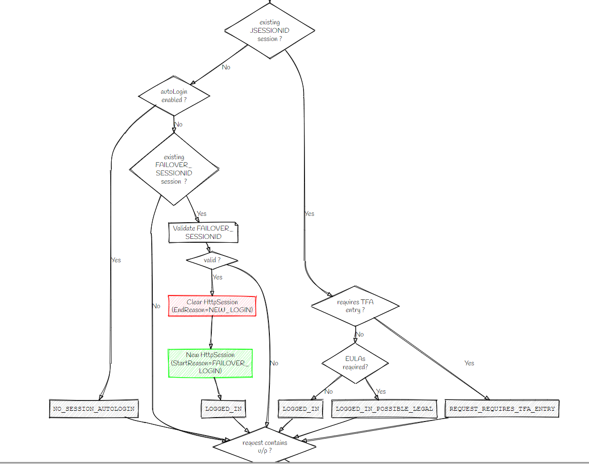
java-to-graphviz takes your java source code and converts it into graphviz diagrams.
This is the sort of thing you might want to do when you take a look at some piece of code and realise it's a completely unmaintainable mess but it still needs to be documented somehow.
You can annotate the generated diagram using specially-formatted comments.
Here's the type of output it can produce:
| AST node | Sample code | Diagram |
|---|---|---|
| Block | // gv-graph |
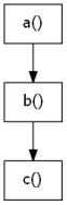 |
| If | // gv-graph |
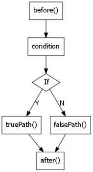 |
| For | // gv-graph |
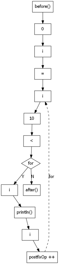 |
| EnhancedFor | // gv-graph |
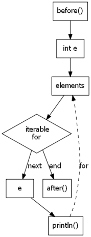 |
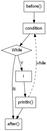
| While | // gv-graph |
 |
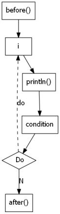
| Do | // gv-graph |
 |
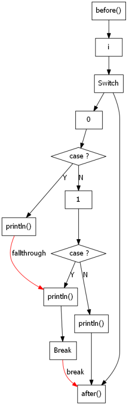
| Switch | // gv-graph |
 |
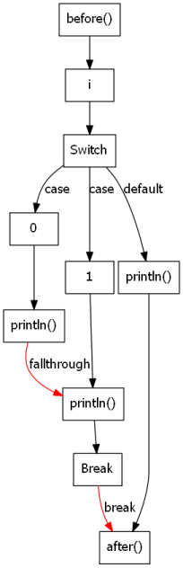
| Switch (alternate) |
// gv-graph |
 |
| InfixExpression | // gv-graph |
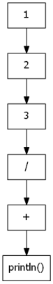 |
| UnaryExpression | // gv-graph |
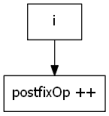 |
| TernaryExpression | // gv-graph |
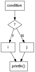 |
| InfixExpression (boolean shortcut) | // gv-graph |
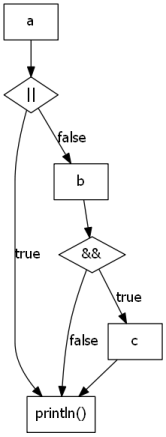 |
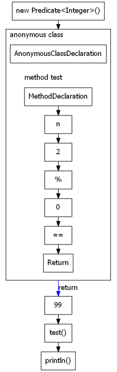
| AnonymousClassDeclaration | // gv-graph |
 |
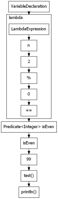
| LamdaExpression | // gv-graph |
 |
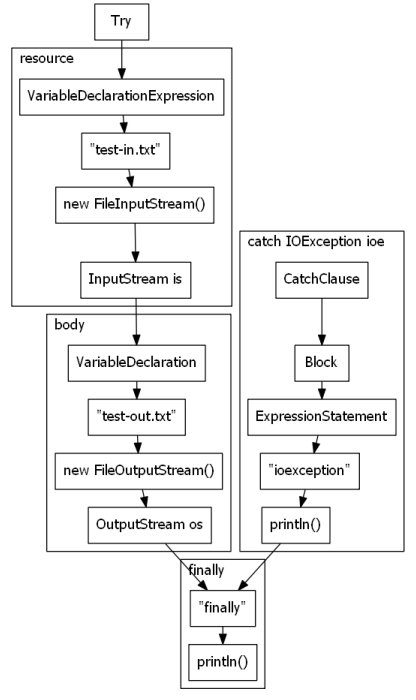
| TryStatement (with resources) | // gv-graph |
 |
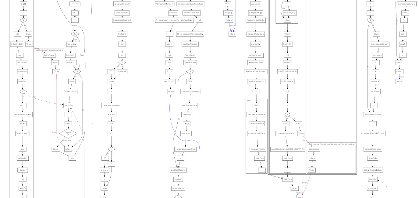
and this is what it looks like when you string that all together:
You obviously won't want that, so it suppresses nodes by default, to give you just the nodes you're interested in.
Theres' a few different stages in the pipeline.
-
Parse source file into an Abstract Syntax Tree (AST). This uses the eclipse parser, so should be able to handle the newer java language features, such as lambdas and inner classes. I'm aware inner classes were added back in the java 1.2 era so probably isn't considered a new language feature any more.
-
Extract comments. For reasons of efficiency, the eclipse parser doesn't store comments in the AST tree where the comments actually appear, they're in a separate list. We scan this list for "gv" comments, and attribute the comment to the AST node it refers to.
-
Generate Directed Acyclic Graph (DAG). This will store our graphviz representation of the AST, and initially looks very similar to the AST, with some additional metadata. Note it's not strictly a DAG, as we can get loops due to for/while/do constructs, but any edges leading backwards are marked as 'back' edges so we can still treat it as a DAG later by ignoring these edges.
-
Generate edges. This recurses through the DAG and adds control flow edges to it. This may involve rejigging the DAG so that nodes that execute before others are located before them in the diagram.
-
Filter nodes. This recurses through the DAG and removes unnecessary nodes; e.g. "A -> B -> C" segments can be reduced to "A -> C". The filtering occurs around 'keepNodes' which must be kept in the final diagram. Users can control how nodes are filtered and kept using special "gv" comments in the source code.
-
Create DOM. The filtered DAG is converted into a HTML-like document object model (DOM). This represents the DAG structure in terms of "graph", "node" and "edge" elements, with attributes for user-supplied styles and labels, also supplied using special "gv" comments.
-
Apply styles. The DOM has a CSS stylesheet applied to it. JavaToGraphviz comes with a few builtin stylesheets, but you can replace or override these in a number of ways. During this step, final node and edge IDs, labels, and formatting are determined. Additionally, extra subgraphs can be added into the diagram, which restructures the DOM and adds subgraphs into the DAG.
-
Extract styles. The applied styles in the DOM are copied back into the DAG.
-
Create DOT. The DAG is converted into graphviz "dot" syntax, which can then be used as input to the graphviz "dot" program to create the final diagram.
The general gist of the thing is that you can add comments inside your source code in order to shape the diagram that's generated.
Those comments start with "gv:" ( or variations on that ) to differentiate them from your normal run-of-the-mill commentary.
The gv directives can be one of the following:
| Syntax | Example | Description |
|---|---|---|
| // gv: | // gv: open box |
override the label for a node. If on it's own line can add additional nodes to the diagram |
| // gv: { css } | // gv: open box { color: green; shape: oval; } |
override the label for a node, and supply additional formatting. The formatting is expressed as a CSS rule, but uses graphviz attribute names rather than the usual CSS property names |
| // gv#id: | // gv#openBox: open box |
override the ID for a node. This can be used to make the graphviz output more understandable, or to apply styles in a separate stylesheet |
| // gv.class: | // gv#openBox.green.oval: open box |
add CSS classes to a node. This can be used to make the graphviz output more understandable, or to apply styles in a separate stylesheet. Many classes may be assigned to a node, but only a single ID. Additional classes may be added by other parts of JavaToGraphviz (e.g. a class representing the node type is added when the DAG is constructed, so that all "if" nodes can later be shaped as diamonds ) |
| // gv-style: { rules } | /* gv-style: { |
defines CSS style rules. Most CSS property names correspond to graphviz attribute names, but those beginning with "gv-" are processed within JavaToGraphviz instead. |
| // gv-style: { @import } | // gv-style: { @import "JavaToGraphviz.css"; } |
import a CSS stylesheet. To find the stylesheet, the classpath is searched first, then the local filesystem |
| // gv-keepNode: spec | // gv-keepNode: expressionStatement block |
Changes the 'keepNode' flags when creating DAG nodes. If the default keepNode value is true, then individual nodes can be excluded by prefixing them with a minus sign; e.g. // gv-keepNode: -expressionStatementAlso note that any node that has a // gv: commentwill be kept, regardless of the keepNode flags. |
| // gv-literal: dot | // gv-literal: { rank = same; case1; case2; } |
Adds graphviz 'dot' code directly into the final graphviz diagram |
| // gv-subgraph | // gv-subgraph: something noteworthy |
Starts a subgraph in the diagram. Subgraphs can have borders and other formatting applied, and can be used to highlight different parts of the code. Subgraphs can be nested. |
| // gv-endSubgraph | // gv-endSubgraph |
Closes a subgraph You probably want to do this at the same depth in the AST tree; e.g. in the same block that opened the subgraph. |
| // gv-graph | // gv-graph: something separate |
Starts a new graphviz diagram. The first time this is encountered, everything before this line is discarded, and this line marks the beginning of a new diagram. If omitted, the entire class/interface is drawn. |
| // gv-endGraph | // gv-endGraph |
Closes a graph. Nodes will not be processed until a new graph is created with gv-graph. |
| // gv-option key=value | // gv-option: centralSwitch=true |
Options can be used to change how JavaToGraphviz creates nodes and edges |
Here's all that again in a bit more detail.
To change the label on the diagram, supply some text after the "gv:", e.g.
orderDonuts(); // gv: order some donuts
would appear as
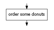
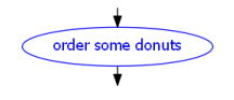
You can include individual style rules on the "gv:" comment by putting them in curly braces; e.g.
orderDonuts(); // gv: order some donuts { shape: oval; color: blue; fontcolor: blue; }
You can also apply styles to various nodes using the graphviz equivalent of CSS, in which style rules are defined in a "gv-style:" block, and then classes and IDs are assigned to AST nodes in your gv comments to apply those rules.
I'm using a real CSS parser here, so all the fiddly bits around specificity should apply to those rules, assuming you know them, which you should if you're born any time past the 1990s.
e.g.
/* gv-style: {
// some rules
.something { color: red; }
.special { color: green; }
#unique { shape: hexagon; }
}
*/
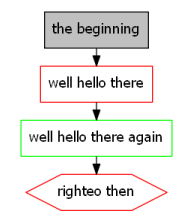
before(); // gv: the beginning { fillcolor: grey; }
someCode(); // gv.something: well hello there
someOtherCode(true); // gv.something.special: well hello there again
someOtherCode(false); // gv#unique.something: righteo then
would appear as:
Note !important rules aren't implemented yet.
Those styles are applied to a pretend DOM that is created separate from the graphviz diagram; the style rules you create are applied to the imaginary DOM and then the calculated styles are used in the generated diagram.
The DOM looks a little bit like the AST of the program, but different. Here's a snippet before styles are applied.
<html>
 <head></head>
 <body>
  <graph>
   <graphNode></graphNode>
   <graphEdge></graphEdge>
   <node id label classname="ForStatement" class="typeDeclaration class">
    <node id label class="simpleName"></node>
    <node id label methodname="testFor" class="methodDeclaration">
     <node id label class="simpleName"></node>
     <node id label class="block">
      <node id label=" start of method" class="comment"></node>
      <edge></edge>
      <node id label class="for">
       <node id label type="int" class="initialiser variableDeclarationExpression">
        <node id label variablename="i" type="int" class="variableDeclarationFragment">
         <node id label class="simpleName"></node>
         <node id label literalvalue="0" class="numberLiteral literal"></node>
         <edge></edge>
        </node>
        <edge></edge>
       </node>
       <edge></edge>
       <node id label operatortoken="<" operatorname="InfixExpression$Operator" class="expression infixExpression">
        <node id label name="i" class="simpleName"></node>
        <edge></edge>
        <node id label literalvalue="12" class="numberLiteral literal"></node>
        <edge></edge>
       </node>
There are some elements and attributes in that DOM which are created automatically from the Java source, those are:
| Element | Description |
|---|---|
| html, head, body | These HTML elements exist solely so that I can use the jsoup CSS selector code to apply CSS rules to the DOM |
| graph | The graph element represents an entire graphviz diagram. Styles applied to this node are set on the graphviz digraph |
| graphNode | The graphNode element represents the default node styles. Styles applied to this node are set on a node object in the digraph. Note you could also apply styles to all nodes by using a .node selector in a CSS rule. There's pros and cons to each approach. |
| graphEdge | The graphEdge element represents the default edge styles. Styles applied to this node are set on an edge object in the digraph. Note you could also apply styles to all edges by using an .edge selector in a CSS rule. There's pros and cons to each approach. |
| node | Each node represents a node in the DAG, which usually represents a node in the AST. nodes created from AST nodes will have a class attribute containing the AST type ( e.g. methodDeclaration for a MethodDeclaration ) |
| edge | Each edge represents an edge in the DAG. Edges may have other classes assigned by the specific Edger implementation ( e.g. the ControlFlowEdger will add 'true' and 'false' classes to edges leading out of 'if' nodes ) |
There are a few standard attributes on every node / edge:
| Attribute | Description |
|---|---|
| id | Each node has an id attribute which can be used to select that node from external CSS. If blank, it will be set using gv-idFormat rules in the CSS |
| label | Each node has a label attribute which populates the graphviz 'label' attribute. If blank, it will be set using gv-labelFormat rules in the CSS |
| class | Each node and edge may have additional classes defined by the Edger or by the user in gv comments |
| style | Each node and edge may have additional styles defined by the user in gv comments |
Attributes added to various nodes by the ControlFlowEdger.
These attributes can also be referenced within gv-idFormat and gv-labelFormat style rules using ${xxx} syntax.
| nodeType className | Attribute | Attribute value |
|---|---|---|
| typeDeclaration | className | The name of the Java class |
| typeDeclaration | interfaceName | The name of the Java interface |
| methodDeclaration | methodName | The name of the method |
| catchClause | exceptionSpec | The type and name of the caught exception |
| variableDeclaration | type | The type of the variable ( is repeated on each variableDeclarationFragment ) |
| variableDeclaration | variableName | The name of the variable |
| singleVariableDeclaration | type | The type of the variable |
| singleVariableDeclaration | variableName | The name of the variable |
| booleanLiteral, numberLiteral, characterLiteral, nullLiteral, typeLiteral, stringLiteral | literalValue | The literal value in the source code |
| constructorInvocation | methodName | "this" |
| superConstructorInvocation | methodName | "super" |
| methodInvocation | methodName | the method name |
| superMethodInvocation | methodName | qualifier + ".super." + method name |
| infixExpression | operatorToken | the operator token ( wip, will be "*", "/", "||" etc ) |
| infixExpression | operatorName | a more css-friendly operator name ( wip, will be "times", "divide", "conditionalOr" etc ) |
| postfixExpression | operatorToken | the operator token ( wip, will be "++" etc ) |
| postfixExpression | operatorName | a more css-friendly operator name ( wip, will be "increment" etc ) |
| prefixExpression | operatorToken | the operator token ( wip, will be "++" etc ) |
| prefixExpression | operatorName | a more css-friendly operator name ( wip, will be "increment" etc ) |
| castExpression | type | the type being cast to |
| instanceofExpression | type | the right operand type name |
| assignment | operatorToken | the operator token ( wip, will be "=", "+=" etc ) |
| assignment | operatorName | a more css-friendly operator name ( wip, will be "assign", "plusAssign" etc ) |
| fieldAccess | fieldName | the name of the field |
| superFieldAccess | fieldName | qualified super field |
| classInstanceCreation | type | the type of the class being created |
| arrayCreation | type | the type of the array being created |
| variableDeclarationExpression | type | The type of the variable |
| name | name | the fully qualified name |
| thisExpression | name | qualified this |
| creationReference, expressionMethodReference, superMethodReference, typeMethodReference | name | reference name |
Attributes added to various edges by the ControlFlowEdger.
These attributes can also be referenced within gv-labelFormat and gv-xlabelFormat style rules using ${xxx} syntax.
| nodeType className | Attribute | Attribute value |
|---|---|---|
| break | breakLabel | if a target label was included in the break statement, that target label, otherwise an empty string |
| continue | continueLabel | if a target label was included in the continue statement, that target label, otherwise an empty string |
Classes added to various nodes and edges by the ControlFlowEdger:
| nodeType className | Element | className | Description |
|---|---|---|---|
| typeDeclaration | node | interface | The type declaration is for an interface |
| typeDeclaration | node | class | The type declaration is for a class |
| - | node | method, end | An artifical node is created at the end of each methodDeclaration ( so that all the 'return' edges have something to flow to ), which has method and end classes |
| break | edge | break | The edge from a break statement will have the break class |
| continue | edge | continue | The edge from a break statement will have the continue class |
| return | edge | return | The edge from a return statement will have the return class |
| throw | edge | throw | The edge from a throw statement will have the throw class |
| if | edge | if, true | The edge connecting an if expression to the if body will have if and true classes |
| if | edge | if, false | The edge connecting an if expression to the else body (or the next statement if there is no else) will have if and false classes |
| for | edge | for, true | The edge connecting a for expression to the repeating block will have for and true classes |
| for | edge | for, false | The edge connecting a for expression to the next statement will have for and false classes |
| for | edge | for, back | The back edge connecting the end of a repeating block back to the loop updater nodes will have for and back classes |
| enhancedFor | edge | enhancedFor, true | The edge connecting an enhancedFor expression to the repeating block enhancedFor and true classes |
| enhancedFor | edge | enhancedFor, false | The edge connecting an enhancedFor expression to the next statement will have enhancedFor and false classes |
| enhancedFor | edge | enhancedFor, back | The back edge connecting the end of a repeating block back to the loop iterator will have enhancedFor and back classes |
| while | edge | while, true | The edge connecting a while expression to the repeating block will have while and true classes |
| while | edge | while, false | The edge connecting a while expression to the next statement will have while and false classes |
| while | edge | while, back | The back edge connecting the end of a repeating block back to the while condition will have while and back classes |
| do | edge | do, back, true | The back edge connecting a do expresson to the start of the repeating block will have do, back and true classes |
| do | edge | do, false | The edge connecting the end of a repeating block to the next statement will have do and false classes |
| switch | node | centralSwitch | If the 'centralSwitch' option is true, then the switch node will have the centralSwitch classes.When this option is in effect, all switch cases originate from the switch node, otherwise a series of if-like case nodes are created. |
| switchCase | node | centralSwitch | Is set if 'centralSwitch' is true |
| switchCase | edge | switchCase | If the 'centralSwitch' option is true, the edge from the switch node to the switchCase node will have the switchCase class |
| switchCase | edge | switchCase, true | If the 'centralSwitch' option is false, the edge from the switchCase node to the switchCase body will have the switchCase and true classes |
| switchCase | edge | switchCase, false | If the 'centralSwitch' option is false, the edge from the switchCase node to the next switchCase node will have the switchCase and false classes |
| switchCase | edge | switchCase, default | The default case will have switchCase and default classes |
| switchCase | edge | switch, fallthrough | A fallthrough edge from one switch case to the next will have switch and fallthrough classes |
| switch | edge | switch, false | If the switch does not have a default case, an edge from the switch node to the next statement will have the switch and false classes |
| lambdaExpression | edge | lambdaEntry | The edge from the lambdaExpression node to the block will have a lambdaEntry class |
| - | node | lambdaExpression, end | An artifical node is created at the end of each lambdaExpression ( so that all the 'return' edges have something to flow to ), which has lambdaExpression and end classes |
| booleanLiteral, numberLiteral, characterLiteral, nullLiteral, typeLiteral, stringLiteral | node | literal | All literalExpression subclasses have a literal class |
| constructorInvocation | edge | invocationArgument | the edges between argument expressions in a constructor will have an invocationArgument class |
| superConstructorInvocation | edge | invocationArgument | the edges between argument expressions in a super constructor will have an invocationArgument class |
| methodInvocation | edge | invocationArgument | the edges between argument expressions in a method call will have an invocationArgument class |
| superMethodInvocation | edge | invocationArgument | the edges between argument expressions in a super method call will have an invocationArgument class |
| infixExpression ( &&, || ) | node | infixConditional | shortcut infix expressions (that may not evaluate the second expression) have an infixConditional class |
| infixExpression ( || ) | edge | infixConditional, true | for shortcut 'or' expressions, the 'true' edge that shortcuts the next expression |
| infixExpression ( || ) | edge | infixConditional, false | for shortcut 'or' expressions, the 'false' edge that evaluates the next expression |
| infixExpression ( && ) | edge | infixConditional, true | for shortcut 'and' expressions, the 'true' edge that evaluates the next expression |
| infixExpression ( && ) | edge | infixConditional, false | for shortcut 'and' expressions, the 'false' edge that shortcuts the next expression |
| conditionalExpression ( ? ) | edge | conditionalExpression, true | for '?' expressions, the 'true' edge connecting the condition to the true expression |
| conditionalExpression ( ? ) | edge | conditionalExpression, false | for '?' expressions, the 'false' edge connecting the condition to the false expression |
| classInstanceCreation | edge | invocationArgument | the edges between argument expressions in a 'new' expression will have an invocationArgument class |
| arrayInitializer | edge | invocationArgument | the edges between array element expressions in an array initializer |
| - | node | anonymousClassDeclaration, end | An artifical node is created at the end of each anonymousClassDeclaration, so that we can draw a transparent edge from the end of each method to that node, which helps make the diagram look pretty. |
| - | edge | anonymousClassDeclarationEnd | The artificial edge from the end of each method to the artifical node. This isn't a control flow edge, so should be transparent in the CSS. |
| anonymousClassDeclaration | edge | anonymousClassDeclarationBegin | The edge from the anonymous class declaration node to the start of each method/field declaration in that class |
| ast | node | ast | All unrecognised nodes will be edged by the AstEdger, and have an 'ast' class. You shouldn't see any of these in the ControlFlowEdger any more |
classNames in the DOM that are generated from AST nodes are listed below. These classNames are the eclipse parser AST class name name with the word "Statement" removed and their first letter lower-cased; e.g. IfStatement nodes are given the className 'if'. ExpressionStatements retain the "Statement" suffix, to differentiate ExpressionStatements from Expressions.
typeDeclarationmethodDeclarationvariableDeclarationFragmentblocksynchronizediftryforenhancedForswitchswitchCasebreakwhilecontinuedoreturnthrowcatchClauselabeledexpressionStatementvariableDeclarationsingleVariableDeclarationconstructorInvocationsuperConstructorInvocationassertemptycomment
All expressions are subclasses of Expression. The expression classNames are:
- literal-ish
- name-ish
- control flow-ish
- evaluation-ish
- creation-ish
variableDeclarationExpressionarrayCreationarrayInitializerclassInstanceCreation( also control flow-ish )
- access-ish
- modification-ish
Note this still isn't a complete list of all AST nodes yet, but it's most of them.
Artifical nodes created by the ControlFlowEdger are:
| className | Description |
|---|---|
| methodDeclarationEnd | added to the end of methodDeclaration blocks, all return and throw edges will connect to this node |
| lambdaExpressionEnd | added to the end of lambdaExpression blocks, all return and throw edges will connect to this node |
| anonymousClassDeclarationEnd | added to the end of anonymousClassDeclaration blocks, all methods within the anonymous class will have an invisible edge connected to this node for layout purposes ( these should be styled as transparent or invisible as they're not part of the control flow diagram ) |
| infixExpressionCondition | added within shortcut infixExpression nodes to branch the control flow based on the value of the left-hand-side operand |
Debug attributes added to various nodes by the DagStyleApplier.
These attributes can be referenced within gv-idFormat, gv-labelFormat and gv-xlabelFormat style rules using ${xxx} syntax, but can't be used in CSS selectors. Most of these are only appear in the JavaToGraphviz-debug.css stylesheet, apart from ${lineNumber} which is used in all stylesheets.
| Attribute | Description |
|---|---|
| lineNumber | The starting line number of this node in the source code. As these line numbers are used to generate default IDs, they are suffixed with an incrementing integer to allow multiple nodes on the same source line. e.g. "100", "100_2", "100_3" etc |
| nodeType | The AST node type |
| keepNode | "true" if this node is a keeper, "false" otherwise |
| lastKeepNodeId | the id of the last seen node connected to this node with keepNode="true" |
| numComments | the number of gv comments attributed to this node |
Users can create CSS rules based on the values of these elements, attributes and classes, which are then applied to the DOM and merged with the any 'style' attributes.
Most properties correspond to graphviz attributes; see the Graphviz documentation for a complete list of these.
Some additional properties are handled by JavaToGraphviz itself, these are all namespaced with a "gv-" prefix.
Prefixed properties include:
| Property | Description |
|---|---|
| gv-idFormat | The gv-idFormat is used to assign IDs to nodes. These IDs are visible in the DOM, and in the generated graphviz diagram. Other attributes can be included in the idFormat by specifying their name in curly brackets, For example, the stylesheet node { will assign an ID of "s_" followed by the line number of the node, or "if_" for nodes representing 'if' statements. As these ${lineNumber}s are used to generate default IDs, they are suffixed with an incrementing integer to allow multiple nodes on the same source line. |
| gv-labelFormat | The gv-labelFormat is used to assign labels to nodes. These IDs are visible in the DOM, and in the generated graphviz diagram. Other attributes can be included in the idFormat by specifying their name in curly brackets, similar to the gv-idFormat. The labelFormat may include the id, or the id may include the label, but they may not include each other. |
| gv-wordwrap | The gv-wordWrap property can be used to force newlines to be added into the node label. This is useful for some graphviz shape types ( e.g. diamond ), which become overly stretched if their label is wide. |
| gv-newSubgraph | Create a new subgraph 'underneath' the selected element |
| gv-beginOuterSubgraph | Create a new subgraph 'above' the selected element, then move the selected element and all nodes to gv-endSubgraph into that subgraph |
| gv-endOuterSubgraph | Marks the end of the subgraph created by gv-beginOuterSubgraph. |
| gv-truncateEdges | Either "incoming", "outgoing", "none" or "both". Will truncate the edges leading into or out of a subgraph. Must be applied to the same element that had the gv-newSubgraph property. Edges will begin/end outside the subgraph boundary |
| gv-xlabelFormat | Similar to gv-labelFormat but sets the xlabel attribute, which causes the label to be ignored during graphviz edge routing |
Note that the gv-newSubgraph style property ( defined in the CSS ) is not the same as the gv-subgraph directive discussed earlier ( defined in the source code ), although they perform similar tasks. The gv-newSubgraph CSS property allows subgraphs to be created by matching style rules ( e.g. enclosing all try/catch/finallys in a subgraph rectangle ) whereas the gv-subgraph directive allows the user to specify one-off subgraphs in their source code to highlight specific blocks of code.
This combination of elements, attributes and properties means you can turn all your 'if' statements to diamonds via:
/* gv-style: { .if { shape: diamond; } } */
Typically each method in a class is graphed as it's own subgraph.
You can also construct subgraphs within methods to highlight or separate various nodes in the diagram. These subgraphs are created using some special CSS rules which affect the DOM.
So for example, you could put all your try/catch statements in subgraphs via
/* gv-style: {
    node.try { gv-newSubgraph: true; }
    node.try > subgraph {
      // subgraph ids must being with the text "cluster_" for graphviz to draw it as a subgraph
      gv-idFormat : "cluster_t_${lineNumber}";
      gv-labelFormat : "try";
      pencolor : black;
      labeljust : "l";
    }
} */
but you probably want to put the 'tryResources', 'tryBody', 'catchClause' and 'finally' classes in subgraphs instead; see JavaToGraphviz.css
You can also create subgraphs to highlight a particularly exciting bit of Java source code; e.g.
System.out.println("I like traffic lights");
System.out.println("I like traffic lights");
System.out.println("I like traffic lights");

// gv-subgraph: full orchestral backing

System.out.println("I like traffic lights");
System.out.println("I like traffic lights");
System.out.println("I like");

// gv-endSubgraph

System.out.println("traffic lights");
CSS doesn't normally allow you do modify the DOM ( ignoring ::content pseudo-elements ), so in order to be able to style the DOM elements that are created by these CSS rules, there are multiple passes of the CSS.
- JavaToGraphviz-base.css - base CSS ; bare minimum to prevent graphviz errors
- JavaToGraphviz-debug.css - debugging CSS ; all node labels include lineNumber, nodeType and lastKeepNodeId
- JavaToGraphviz.css - default CSS ; uses most of the classes and attributes listed above
The java-to-graphviz-cli.jar can be used to generate diagrams from a command line. There's a few options you can supply:
C:\>java -jar java-to-graphviz-cli.jar
Usage:
  java -jar java-to-graphviz-cli.jar [options] filename filename ...

where [options] are:
 -h -?                       display this help text
 --verbose  -v               increase verbosity ( info level )
 --verbose2 -vv              increase verbosity a bit more ( debug level )
 --format   -f dot|dom1|dom2 output format: DOT diagram (default), pre-styled DOM, post-styled DOM
 --output   -o filename      send output to filename
                             For multiple output files, filename can contain
                               {basename} for base filename, {index} for diagram index
                             e.g. "{basename}-{index}.dot" for dot output,
                                  "{basename}.html" for dom output
                             default is stdout
 --source   -s version       set Java source language version ( 1.0, 1.1, 1.2, 1.3, 1.4, 1.5, 1.6, 1.7,
                               8, 9, 10, 11, 12, 13, 14, 15, 16 )

 --base-css -b url           replace base css with url ( relative to classpath, then file:///./ )
                               default = JavaToGraphviz.css
 --user-css -u url           add url to list of user css imports
 --css      -c {rules}       add css rules

 --option   -p key=value     set initial option; can be modified in source by 'gv-option' and 'gv-keepNode' directives

Options keys and defaults:
 edgerNamesCsv=control-flow  csv list of edger names
                             possible edger names: control-flow, ast
 enableKeepNodeFilter=false  if true, will perform node filtering
 defaultKeepNode=true        if true, filter will keep nodes by default
 keepNode=                   space-separated nodeTypes for fine-grained keepNode control
                             prefix nodeType with '-' to exclude, '+' or no prefix to include
                               e.g. "-expressionStatement -block -switchCase"
                               to exclude those nodeTypes when defaultKeepNode=true
                             NB: any node with a 'gv' comment will always be kept
e.g.
C:\>java -jar java-to-graphviz-cli.jar --base-css https://raw.githubusercontent.com/randomnoun/java-to-graphviz/master/src/main/resources/JavaToGraphviz.css src\test\java\com\example\input\ForStatement.java
digraph G {
  node [
    shape = rect;
    fontname = "Handlee";
  ]
  edge [
    fontname = "Handlee";
  ]
  bgcolor = transparent;
  fontname = "Handlee";
  compound = true;
  s_19 [
    class = "methodDeclaration";
    label = "MethodDeclaration";
    fillcolor = white;
    style = filled;
  ];
  s_19_3 [
    class = "block";
    label = "Block";
    fillcolor = white;
    style = filled;
  ];
...
To incorporate java-to-graphviz into your maven build, use the java-to-graphviz-maven-plugin
DONE
- style rules
- external style refs (classpath, TODO urls, files)
- label formats
- css-defined subgraphs
- comment-defined subgraphs
- a single .java source file can contain multiple graphs and subgraphs
- can put literal gv into the diagram
- few builtin methods/style properties/declarations to make this a bit easier to generate diagrams; e.g. wordwrap, flip logic on if edge labels, alternate representations, probably others
- comment attribution
- bit of flexibility when it comes to how the diagram is generated ( node suppression , artificial nodes, that sort of thing )
- seeing I"m going to the trouble of creating a DOM to apply styles maybe dump that as well, &/or the AST tree. apply styles to AST nodes vs dag nodes ?
- lambdas, anonymous classes, and example images in the readme
- a maven plugin to generate these things during your build process.
TODO
So a few things that'd be nice to implement if I get around to it:
- bunch up the exit nodes if there's lots of them
- a maven plugin which colours in the nodes using jacoco output.
- another eclipse plugin which hooks in via JVMTI to do that in realtime.
- another plugin which annotates the nodes with generated bytecodes.
- another plugin which adds in AOP nodes.
- create a stylesheet with no labels and shaded nodes. Maybe use whatever colouring scratch uses.
- and so on.
Some example Java sourcecode, and the generated graphviz DOT and PNG output, from the unit tests:
The compact graphviz and PNG outputs are generated from the same source file, with the defaultKeepNode option set to false.
Here's the writeup on the blog.
java-to-graphviz is licensed under the BSD 2-clause license.