clock module
Goal
- build a time counter?
- one can control how fast it flush?
stuff
log
<2020-05-19 Tue>
Five months in, zero progress in physical assemble. Gradually picking up the peace. Slowly but surely.
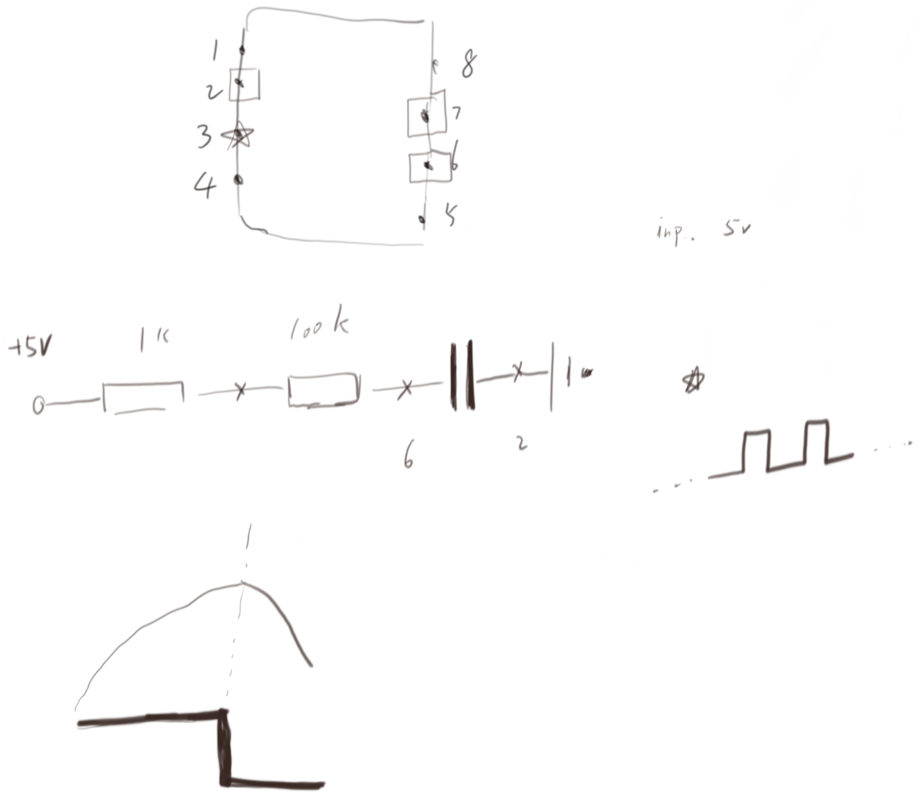
First thing I know is that we have a frequency producer from electricity. How can I transfer it to a controllable sparking stars?
<2020-05-20 Wed> reading how the circuit works.
Nature is continues, human make white and black.
I think it is the tweak between point 6 and 2 makes the capacity charges and discharges back and forth. And during this change, voltage has a periodic feature between points (two of 7,6,2). And the rules say that if the detected voltage is higher, then the output is 1; otherwise 0.
<2020-05-26 Tue>
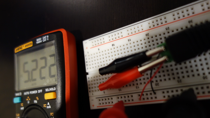
Today, I start to build the real thing. I took the wire from a old mouse, connecting it with the 5 DC voltage convert in such a way that I don’t feel very comfortable.
<2020-05-27 Wed> flush the LED
- State “TODO” from “HOLD” [2020-05-30 Sat 22:27]
- video on youtube: https://www.youtube.com/watch?v=8nzgkSlCKlo
Follow Ben’s watch was easy. I do have issue to understand how the breadboard’s connection at first. I miss understand the wires parallel connected to the 1k resistor and capacitor short the circuit. It did not.
- video on youtube: https://www.youtube.com/watch?v=oFcDTblaUVs
After Ben’s connection, I made my own version.
<2020-05-30 Sat> read internal diagram of IC555
<2020-06-03 Wed> improve the voltage source connector and reading some about circuit
- start to learn common emitter (CE), common collector (CC), and common base (CB)
- start to read RS FF within transistor
<2020-06-05 Fri> understand the role of NPN in IC555
<2020-06-06 Sat> install adjustable blinking frequency controller
I had an issue for choosing the right resistor between 555’s pin-7 and pin-6. Previous to this point, I installed an 1 M Ohm and I found a equal blinking frequency. However, the teacher has a 100k Ohm resistor, which I do not have.
I did a test using a 220 Ohm resistor and I found the LED stayed on but not blinking. Then I check the document and found the relation between t1 and t2. It can have a relation as t1/t2= 1 + R_A + R_B. This indicates that if R_B is much greater than R_A, then the gap between LED on and off should equal. This was what happen when I installed a 1 M Ohm resistor in between 555’ pin-6 and pin-7.
<2020-06-07 Sun> build monostable clock
The monostable clock means that you push the button, the LED flushes; released closed. It took me a while to find the bad connection in momentary pushbutton.
As I march on the third clock, I did not make it successfully. The slide switch is different from the teacher’s circuit. I need to further study how to tweak SR latch to make this final clock.
<2020-06-08 Mon> debug monostable clock
I checked the circuit many times yesterday and today, and I could not make the monostable clock flushing. I even test the slide switch to make sure the relation between three pins. I also replaced the IC555 with flushing clock module, and still don’t know why the LED stayed died.
Amazing things happen, during switching these LEDs to make sure they are still functioning. One time, when I install the LED, the LED start to live and stay that state! I suddenly realize that LED is short for Light-Emitting diodes. It’s a diode. It must be installed in the correct direction. Then, I reverse all other LEDs to test it. It is true. How lucky I was, when do know this feature of LED.
<2020-06-09 Tue> finish time module
- Auto mode: https://youtu.be/XRqyO3dbzqk
- Manual control mode: https://youtu.be/s8hCcCtMwFw
Made the time module as a whole package. From a function point of view, the inputs are:
- slide switch: control which mode the user wants
- a button: if the user wants manual control, it is another input that the user gives to the function
Out put is the blue LEDs. To more precise, how LED flushes.
<2020-06-10 Wed> review a bit of memory and register
- a bit of memory
One bit of memory is built by four NAND gates, these four gates create a function that has two inputs and one output.
Suppose one time period, one can turn on and off the set wire of this function. During this time period, one can connect another function to this function. After this time period, the output of this function is alway set the state that is the same as another function.
That’s how four NAND gates remember things.
- register
It’s a combination of Byte and an Enabler.
<2020-06-12 Fri> review bus, decoder, RAM
Bus is “buss”. No, just wires. Decoder is to show all the possible combination of the given bits. A 256 bytes memory need 257 register. The extra one, which is called MAR, is to store the location of RAM.
what’s difference between “static” and “dynamic” RAM?
<2020-06-13 Sat> read article
<2020-06-15 Mon> planing further reading
<2020-06-16 Tue> reading
<2020-06-17 Wed> reading
<2020-06-18 Thu> reading
<2020-06-20 Sat> reading
From https://www.internalpointers.com/post/introduction-virtual-memory
- [X] Computer Hope — Memory
- [X] Peter J. Denning — Before memory was virtual
- [X] Android Authority — What is virtual memory?
- [X] Kernel.org — Memory Management
- [X] Operating Systems: Three Easy Pieces — Chapter 18: Paging
- [X] Philippe’s Oppermann — Introduction to Paging
- [X] Computer Science from the Bottom Up — Chapter 6. Virtual Memory
- [X] Dr. John T. Bell — Operating systems, Virtual Memory
- [X] StackOverflow — Do modern OS’s use paging and segmentation?
- [X] StackOverflow — What is thrashing? Why does it occur?
- [X] Wikipedia — Memory address
- [X] Wikipedia — Paging
- [X] Wikipedia — Address space
- [X] Wikipedia — Virtual memory
- [X] Wikipedia — Virtual address space
- [X] Wikipedia — Thrashing
- [X] Wikipedia — Segmentation fault
- [X] ITPro Today — Paging Performance
- [X] Aleph One — Smashing The Stack For Fun And Profit
<2020-06-23 Tue> reading on paper
<2020-06-25 Thu> study openmpi
<2020-06-25 Thu> study openmpi
question
Can we use AC to make the square output?
It’s okay, but the problem is that we need to build a “black box” that is able to change it’s frequency, i.e., how fast the stars blinking.
The beauty of using IC555 is that one can change resistance of resistor to change the blinking frequency.
When 555 working, what is the role of npn transistor that is connected to Q?
(or Explain the role of bipolar junction transistor’s role in IC555.)
If there is zero voltage between Base and Emitter, no matter how high (smaller than breakdown voltage) the voltage between the Collector and Emitter, there is almost zero current in collector.
If the Q is on, the NPN transistor is in active region. The current between the Collector and Emitter exist.

