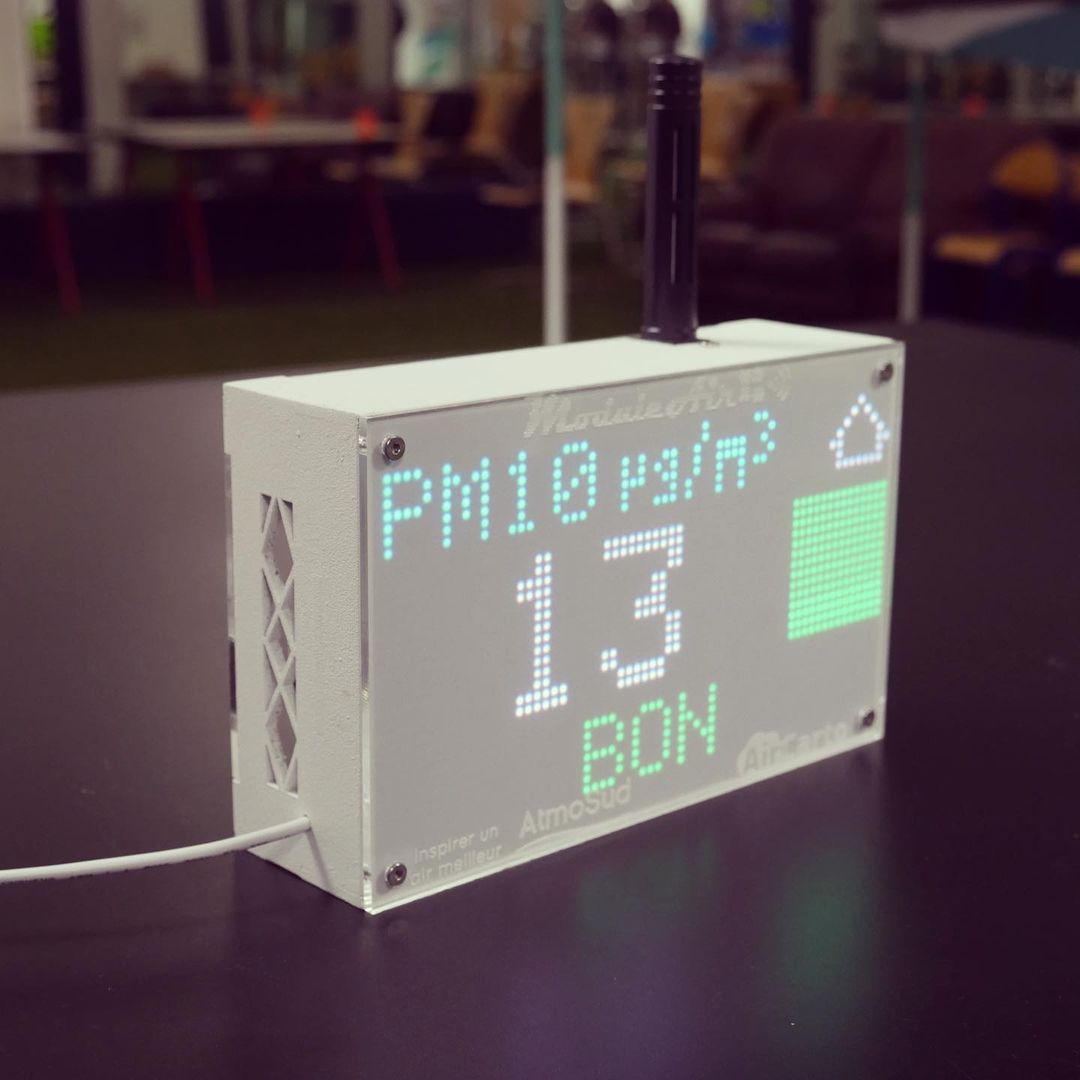
The Module Air is an open source air quality sensor invented by Atmosud and developed by the company AirCarto. The device is equiped with a large LED Matrix Panel to display air quality data measured by inboard sensors.
- Nova PM SDS011 (PM2.5 and PM10)
- Groupe Tera NextPM (PM1, PM2.5 and PM10)
- CCS811 (COV)
- MH-Z16 (CO2)
- MH-Z19 (CO2)
- BME280 (Temperature and Humidity)
- 64x32 RGB Matrix P3 192x96mm
- 64x32 RGB Matrix P2.5 160x80mm
- OLED SSD1306 (not tested)
Attention: some Matrix Panels are not the same and colors can be mixed up, need to change the function display.setColorOrder(RRBBGG);
Small OLED screen can be connected via I2C pins (SDA and SCL).
- Gets measurements from a full range of sensors
- Transmits data with WiFi or LoRaWAN to different databases
- Gets AQ forecasts from the AtmoSud API, the official Institute for Air Quality in SE France
- Displays the measurements and the forecasts (French AQI, NO2, O3, PM10, PM2.5) on the matrix
- Fully configurable through a web interface
- bblanchon/ArduinoJson@6.18.3
- 2dom/PxMatrix LED MATRIX library@^1.8.2
- adafruit/Adafruit GFX Library@^1.10.12
- adafruit/Adafruit BusIO@^1.9.8
- https://github.com/IntarBV/MHZ16_uart
- https://github.com/WifWaf/MH-Z19.git
- sensirion/Sensirion Core@^0.6.0
- mcci-catena/MCCI LoRaWAN LMIC library@^4.1.1
- ThingPulse/ESP8266 and ESP32 OLED driver for SSD1306 displays @ ^4.2.1
- maarten-pennings/CCS811 @ ^12.0.0
And the ESP32 platform librairies:
- Wire
- WiFi
- DNSServer
- WiFiClientSecure
- HTTPClient
- FS
- SPIFFS
- WebServer
- Update
- ESPmDNS
The code is developped on a ESP32 DevC with 38 pins (equiped with a ESP-WROOM-32 module). More information about this board on the official Espressif website.
Please use Platformio to flash the board. The .ini file should be able to get all the needed boards, platforms and libraries from the internet
To force the use of both the SPIs on the ESP32, the SPI library and the PXMatrix library has to be corrected a bit.
SPI.cpp
Modify as this:
#if CONFIG_IDF_TARGET_ESP32
SPIClass SPI(VSPI);
SPIClass SPI_H(HSPI);
#else
SPIClass SPI(FSPI);
#endif
SPI.h
Add this line at the bottom:
extern SPIClass SPI_H;
PxMatrix.h
Replace all SPI with SPI_H except for #include <SPI.h>.
Verify that those pins are defined:
// HW SPI PINS
#define SPI_BUS_CLK 14
#define SPI_BUS_MOSI 13
#define SPI_BUS_MISO 12
#define SPI_BUS_SS 4
The default glcdfont.c of the Adafruit GFX library was modified to add new characters. Copy the content of the glcdfont_mod.c file in the Fonts folder and paste it in the glcdfont.c file in the Adafruit GFX library in the folder of the choosed board in the .pio folder.

You can find the main pin mapping for each board in the ext_def.h file. A list of pin mapping is here. The pin mapping for the LoRaWAN module is in the file moduleair.cpp under the Helium/TTN LoRaWAN comment.

The process is the same as for the Sensor.Community firmware. On the first start, the sation won't find any known network and it will go in AP mode producing a moduleair-XXXXXXX network. Connect to it from a PC or a smartphone and open the address http://192.168.4.1. If needed, the password is moduleaircfg.
For the WiFi connection: type your credentials For the LoRaWAN connection : type the APPEUI, DEVEUI and APPKEY as created in the Helium or TTN console.
Choose the sensors, the displays and the API in the different tabs. For coding reason, it was not possible to use radios for the PM sensors and the CO2 sensors. Please don't check both sensors of the same type to avoid problems…
Please don't decrease the measuring interval to spare connection time.
If the checkbox "WiFi transmission" is not checked, the station will stay in AP mode for 10 minutes and then the LoRaWAN transmission will start. During those 10 minutes or after a restart, you can change the configuration.
If the checkbox "WiFi transmission" is checked, the sensor will be always accessible through your router with an IP addess : 192.168.<0 or more>.<100, 101, 102…>. In that case the data streams will use WiFi and not LoRaWAN (even if it is checked).
The payload consists in a 37 bytes (declared as a 38 according to the LMIC library) array.
The value are initialised for the first uplink at the end of the void setup() which is send according to the LMIC library examples.
0x00, config = 0 (see below)
0xff, 0xff, sds PM10 = -1
0xff, 0xff, sds PM2.5 = -1
0xff, 0xff, npm PM10 = -1
0xff, 0xff, npm PM2.5 = -1
0xff, 0xff, npm PM1 = -1
0xff, 0xff, npm_nc PM10 = -1
0xff, 0xff, npm_nc PM2.5 = -1
0xff, 0xff, npm_nc PM1 = -1
0xff, 0xff, mhz16 CO2 = -1
0xff, 0xff, mhz19 CO2 -1
0xff, 0xff, ccs811 OVC = -1
0x80, bme temp = -128
0xff, bme rh = -1
0xff, 0xff, bme press = -1
0x00, 0x00, 0x00, 0x00, lat = 0.0 (as float)
0x00, 0x00, 0x00, 0x00, lon = 0.0 (as float)
0xff sel = -1 (see below)
Those default values will be replaced during the normal use of the station according to the selected sensors.
The first byte is the configuation summary, representeed as an array of 0/1 bits for false/true:
configlorawan[0] = cfg::sds_read;
configlorawan[1] = cfg::npm_read;
configlorawan[2] = cfg::bmx280_read;
configlorawan[3] = cfg::mhz16_read;
configlorawan[4] = cfg::mhz19_read;
configlorawan[5] = cfg::ccs811_read;
configlorawan[6] = cfg::display_forecast;
configlorawan[7] = cfg::has_wifi;
It produces a single byte which will have to be decoded on server side.
For example:
10101110 (binary) = 0xAE (hexbyte) =174 (decimal) The station as a SDS011, a BME280, a MH-Z19, a CCS811, the forecast are activated, the WiFi is not activated.
The LoRaWAN server has to get the forecast data and transmit by downlink. Because the WiFi is not activated, the uplink sensor data has to be sent to the databases.
If the WiFi is activated, it is useless to decode the uplinks and transmit some downlinks because everything is already done though API calls and POST requests.
The last byte is a selector which tells the LoRaWAN server which kind of downlink value it should transmit (AQ index, NO2, O3, PM10, PM2.5 from the AtmoSud API). 5 downlinks will be sent each day.
Example for transmited data:
{"moduleairid" : "XXXXXXXXXXXXXX", "software_version" : "ModuleAirV2-V1-122021", "sensordatavalues" : [ {"value_type" : "NPM_P0", "value" : "1.84"}, {"value_type" : "NPM_P1", "value" : "2.80"}, {"value_type" : "NPM_P2", "value" : "2.06"}, {"value_type" : "NPM_N1", "value" : "27.25"}, {"value_type" : "NPM_N10", "value" : "27.75"}, {"value_type" : "NPM_N25", "value" : "27.50"}, {"value_type" : "BME280_temperature", "value" : "20.84"}, {"value_type" : "BME280_pressure", "value" : "99220.03"}, {"value_type" : "BME280_humidity", "value" : "61.66"}, {"value_type" : "samples", "value" : "138555"}, {"value_type" : "min_micro", "value" : "933"}, {"value_type" : "max_micro", "value" : "351024"}, {"value_type" : "interval", "value" : "145000"}, {"value_type" : "signal", "value" : "-71"} ]}
Prepare you picture with the format 2:1. Execute:
convert in.png -coalesce -gamma 0.4 -resize 64x32\! -dispose None -interlace None -ordered-dither o4x4,32,64,32 -layers OptimizeFrame out.png
Then go to: http://www.rinkydinkelectronics.com/t_imageconverter565.php
Finally copy/paste the 2048 HEX-bytes in logos-custom.h.
Uplink
function Decoder(bytes, port) {

var buf = new ArrayBuffer(bytes.length);
var view1 = new DataView(buf);
var view2 = new DataView(buf);

bytes.forEach(function (b, i) {
    view1.setUint8(i, b);
});

bytes.forEach(function (b, i) {
    view2.setInt8(i, b);
});


if (view1.getUint8(0) < 0 || view1.getUint8(0) > 255 || view1.getUint8(0) % 1 !== 0) {
      throw new Error(byte+ " does not fit in a byte");
  }

return {"configuration":("000000000" + view1.getUint8(0).toString(2)).substr(-8),"PM1_SDS":view2.getInt16(1).toString(),"PM2_SDS":view2.getInt16(3).toString(),"PM0_NPM":view1.getInt16(5).toString(),"PM1_NPM":view1.getInt16(7).toString(),"PM2_NPM":view1.getInt16(9).toString(),"N1_NPM":view1.getInt16(11).toString(),"N10_NPM":view1.getInt16(13).toString(),"N25_NPM":view1.getInt16(15).toString(),"CO2_MHZ16":view2.getInt16(17).toString(),"CO2_MHZ19":view2.getInt16(19).toString(), "COV_CCS811":view2.getInt16(21).toString(),"T_BME":view2.getInt8(23).toString(),"H_BME":view2.getInt8(24).toString(),"P_BME":view2.getInt16(25).toString(),"latitude":view1.getFloat32(27,true).toFixed(5),"longitude":view1.getFloat32(31,true).toFixed(5),"selector":view2.getInt8(35).toString()};
}
Downlink
function encodeDownlink(input) {
  var selector = parseInt(input.data.selector);
  var value = parseFloat(input.data.value);
  var floatArray = new Float32Array(1)
  floatArray[0]= value;
  var byteArray = new Uint8Array(floatArray.buffer);

  return {
    bytes: [selector,byteArray[0],byteArray[1],byteArray[2],byteArray[3]],
    fPort: input.fPort,
  };
}

function decodeDownlink(input) {

var buf = new ArrayBuffer(5);
var view = new DataView(buf);

input.bytes.forEach(function (b, i) {
    view.setUint8(i, b);
});

  return {
    data: {
      selector: view.getInt8(0).toString(),
      value: view.getFloat32(1,true).toFixed(2).toString()
    }
  }
}