
This was a project to design and build a two-wheeled, self balancing robot that has a compact form factor. The challenge is that shorter the body design, the harder it is for the robot to easily maintain its balance. Since the feasibility of this system is not obvious, first the robot dynamics were solved and used to create a simulation of the system. This simulation was then used to inform the design and component selection process.
This repository contains:
- A python script to the dynamics of the system and determine the equations of motion
- A ROS package that uses the equations of motion to simulate the self balancing robot
- Design files and BOM of the robot
- Arduino script to control the robot.
If you want to use this repository to design your own self balancing robot or just recreate the iteration shown above, follow these steps:
1) Run the file SelfBalancing_AllSymbolic.py.
Requires: python3, sympy, numpy, scipy, and pickle
This file will symbolically solve the Euler-Lagrange equations to derive the equations of motion that characterize a two wheeled, self balancing robot. This will generate a set of pickle files that are used to transfer the equations to the ROS simulation. This file takes about 30 min to fully run due to the amount of symbols being processed, but your mileage may vary. If you would like to see the actual solutions, the raw Latex code is in the 'solutions.txt' file or you can run the print_solutions.py file.
See derivations.pdf in the documentation folder for more information on the system setup and derivation of the equations.
2) Simulate the robot by launching self_balance.launch
Requires: ROS Melodic
This will launch the simulation using the default settings used for the design files in this repo. Once loaded, call the /start service to start the simulation. You will need to update the file_path_params.yaml in the simulate node to update the locations of where to find pickle files you generated earlier.
Package Desciption:
-
dynamics: This package contains all of the files relevant to the computational component of the simulation. Thesimulatenode uses an RK4 integration method combined with the symbolic equations of motion to compute the robot state for every time step. The robot state is then fed into a PID control scheme to compute the required motor torque to keep the robot upright following this control scheme shown below.-
If you would like to customize the simulation to your own parameters, modify the
robot_params.yamlfile to simulate a different robot configuration. These parameters are best pulled from CAD files, see the included CAD mass properties images in the documentation directory for an example. -
To modify the controller gains, change the values in the
controller_param.yamlfile.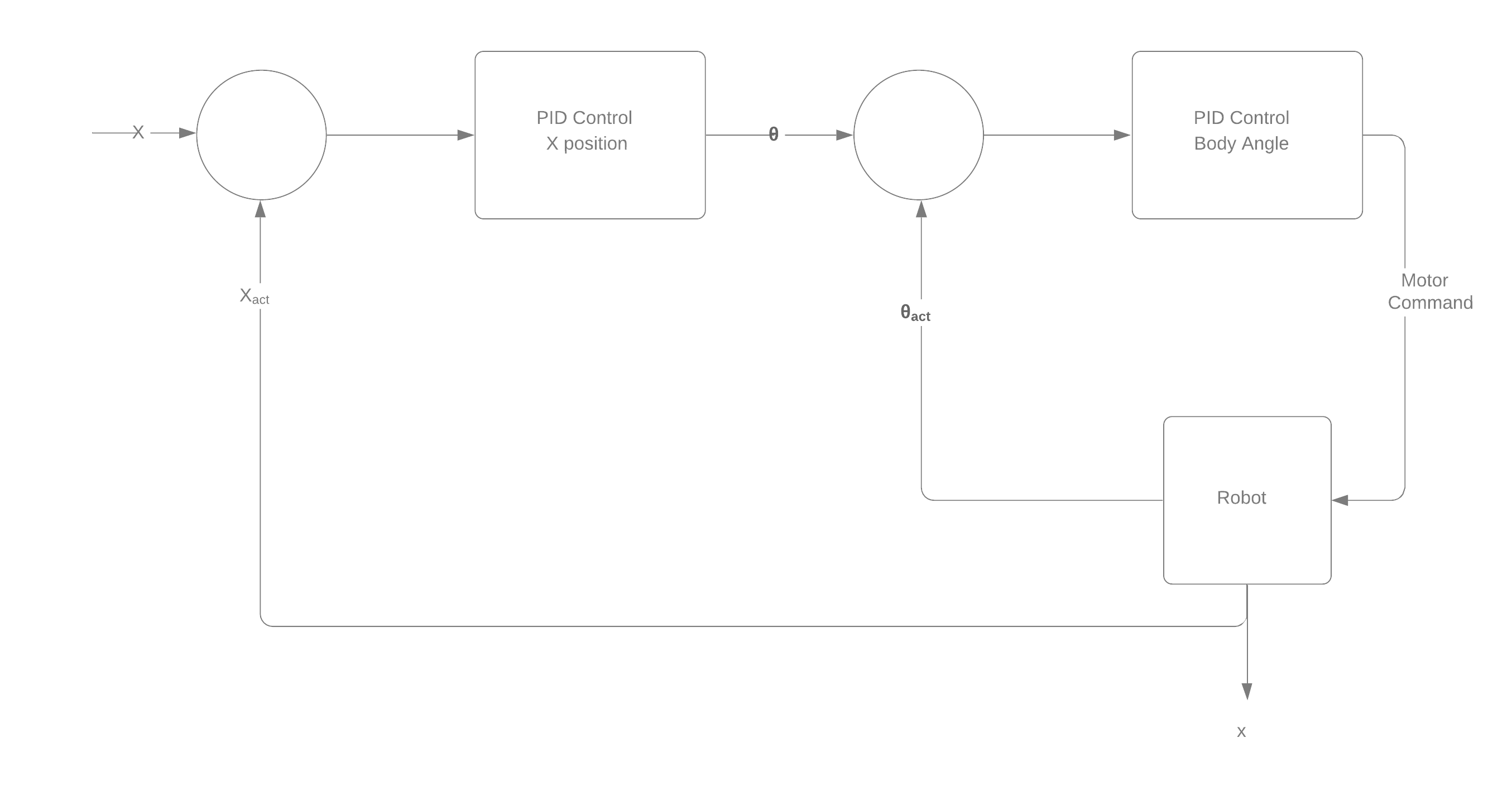
-
-
visualization: This package contains all of the files relevant to the visual component of the simulation. The included launch file displays thebalance_bot.urdf.xacroand is useful if you want to modify the existing model.- To use your own mesh, save an STL for your wheel and an STL for the robot body assembly and place them in the
meshesdirectory. Either call your files the same name or update the file names inside ofbalance_bot.urdf.xacroto match your files.
- To use your own mesh, save an STL for your wheel and an STL for the robot body assembly and place them in the

3) Build it!
The files located in the Prototyping directory should be everything you need to build your own or use the insights discussed below to make your own modifications.
It contains:
- CAD files
- PDFs for laser cutting
- Bill of materials
- Wiring Diagram (shown below)
- Arduino Source Code:
Required libraries: Adafruit BNO055, Adafruit Unified Sensor, EnableInterrupt by Mike Schwager, PID by Brett Beauregard, QuadratureEncoder by Cheng Saetern
There is an extra svg file called motorSpacer.svg that is meant for laser cutting an extra part not currently in the CAD. This piece goes between the motor and the bottom plate so that the encoder wires do not pinch the rotating magnet and stall the motors.
Currently the code does not actually incorporate the encoders to accomplish the position control component of the simulation.

V2 is currently in-progress and the design will be largely the same but incorporating the changes based on the following insights:
-
The actual V1 build came out much heavier than anticipated, this can be attributed to not accounting for the components not in CAD (wires, nuts, screws, etc.) and the 9V battery. This was added late due to the 6V AA pack not being able to reliably power both the Arduino and the motors.
-
The torques and speeds required for this design, are pushing these motors to their design limits. Therefore, any drop below their rated operating voltage of 6V really hurts their ability to output the required control.
-
The IMU used has onboard processing that provides easy access to an absolute position. Since the system is oscillating very quickly the 100Hz data stream may not be quick enough for to allow the motors enough time to react.
-
the IMU fell out of calibration after a few tests and caused the robot to try and balance to a non-vertical position.
-
There is some play in the wheel shaft to the gear box that allows the body to rotate a couple degrees without the motors spinning. Since the window of stable positions is only +/-6 degrees or so, this amount of play is not negligible.
Potential Solutions for V2:
- Switch to aluminum standoff to save weight
- Switch to an Arduino Nano and remove middle plate to save weight
- Switch to 2S Lipo battery to save weight
- integrate a 6V DC-DC regulator to power the motors
- Incorporating encoder-based position control can help counteract the IMU calibration issues
- Simulate V2 design a reevaluate motor selection based on required torques and wheel speeds
- Slight increase of the body height to make the balancing easier and allow the control system more time to react.
This repository is for an active project and a lot of insight was drawn from the first design.
Planned items:
- Integrate simulation functionality for different torques applied to each wheel. This will enable the simulation to turn and eventually follow waypoints.
- Construct a V2 robot that will be able to balance unteathered.
- Incorporate encoders into the V2 control scheme
- Control the physical robot to follow a set of waypoints in 3D space