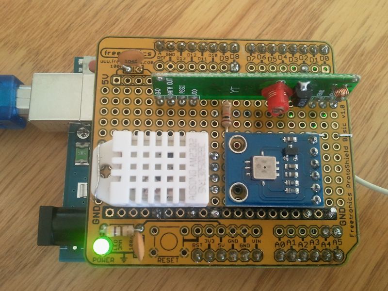
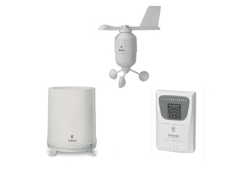
This project allows the 433MHz signals from an Oregon Scientific WMR86 weather station to be intercepted and decoded into simple decimal values using an Arduino Uno. The values for Wind Direction, Wind Speed, Temperature, Humidity, UV Light and Rainfall are then sent via the USB/Serial port on the Arduino to the host computer. In my case I use a Python program to interpret this CSV formatted string of characters and plot the above parameters for display on my website http://www.laketyersbeach.net.au/weather.html (Please note the DHT22 Humidity/Temperature sensor on the Arduino shield is not used in the my final data stream, but is decoded in the software, and so is the temperature read from the BMP05 air pressure detector. The externally mounted OS Temperature/Humidity sensor is used in my final data string. This can be modified to suit your own purposes).
The Arduino listens continually for the three WMR86 sensor's broadcasts (the UV Light sensor must be purchased seperately) and merges them every minute for an output of a CSV string. There are three transmitters in the WMR86 package, Wind Direction+Wind Speed (average and gusts), Temperature+Humidity, and Rainfall (cumulative total and rate). They each have different periods between transmission eg Wind every 14 Seconds, Temp/Hum and Rainfall at longer periods. This does cause overlap of sensor transmissions and inevitable corruption of some packets, however the protocol does have a simple arithmetic checksum based on nybbles that helps eliminate most bad data. Admittedly the chance of substitution errors causing bad data to go un-detected is much higher than if a higher bit CRC based on a polynomial process was used. Range validation would be necessary (in the Python or Arduino) to check if the resulting readings were sensible to improve reliability. This program reports every minute for all three sensors whether a good packet has been received within that minute or not, so the Python program can sum the good and bad packets each minute and report the relative numbers each week in an email.
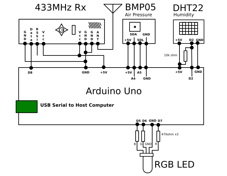
The Wiring: A generic prototyping shield was used.
The Ardunio algorithm to decode the Manchester protocol uses timed delays to sample the waveform from the 433MHz Rx and not interrupts and direct measurement of waveform transitions. This has a number of implications. The main one is that Arduino is continually sampling and analysing the incoming waveform. As it is a dedicated processor in this application and has no other function, this is not a problem. The benefit is that it does simplify the reception and analysis of the waveforms. The simple decoding strategy should also be worth studying by anyone else attempting to leverage other systems that use Manchester encoding. To that end a fairly lengthy explanation is offered below.
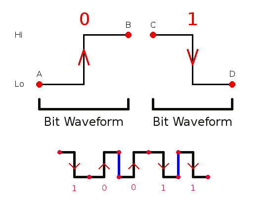
The Manchester protocol is a bias neutral protocol where each bit is composed of a high and low signal of equal length (or close to it). This means that a transmitter can be totally keyed off and on (ie the 433MHz signal is not partially modulated, but is either fully transmitting or 'silent')and no matter what sequences of data, 1's and 0's, are transmitted, on average the Tx signal will consequently be on for the same time as it is off. This means the switching point, or bias level, for the receiver amplifier remains steady. A data bit in a Manchester waveform always has a high and low signal component for encoding both 1's and 0's. So a Bit Waveform for a Data 1 is a high signal followed by a low signal (hi->lo), and a Bit Waveform for a Data 0 is a low signal followed by a high signal (lo->hi). For the OS Weather station each high and low signal duration are both about 430uS. So a full Bit Waveform will last about 860uS. (As will be seen later, the tolerance for decoding these timings is quite wide).
The cheap 433MHz Rx's available have a simple Automatic Gain Control and Bias Detection built in. The AGC allows the sensitivity to be maximised with low signals, and adjusted back when a stronger 433MHz signal is received. The Bias Detection allows the average of the output signal voltage to be determined and applied to one half of a comparator, the other comparator input has the received signal. With Manchester protocol the on/off ratio is equal, so the Bias Detection will be at the average voltage, ie approximately half way, consequently the transitions of the signal from on to off and back again, can produce quite clean, symmetrical logic signals with simple circuitry. This Manchester decoding program relies on the timing of transitions, rather than the exact shape of the waveform (ie again it does not have to be a very clean square wave shape to work, as long as the transitions are accurate).
In other words, the decoding program needs to be able to determine whether it has seen a 430uS 'no signal' followed by a 430uS 'on signal' and so has received a 0, OR has received a 430uS 'on signal" followed by a 430uS 'no signal' and so received a 1. 'on signal' makes the Rx amplifier output go 'hi' and 'no signal' makes the Rx output go 'lo'.
The first very important prior knowledge to have is which of the two polarity conventions for Manchester encoding this system uses. Arguments are put forward for both possibilities as being correct, but either polarity works as good as the other, and with a simple audio sampler, such as Audacity, is simple to work out. The transition polarity used by OS is that a Data 1 is hi->lo and Data 0 is lo->hi.
However any hi->lo transition could be either the middle of a Data 1 Bit Waveform and mean a 1 has been sent, or possibly just the hi->lo transition between two Bit Waveforms, and as such not indicate anything. Similarly any lo->hi could indicate the middle of a Data 0 Bit, or again just a meaningless transition between two Bit Waveforms. The following diagram illustrates the two Bit Waveforms. When these are connected up into a bit stream, then the red dots may or may not require transitions to connect them for the Bit Waveforms to reflect the data bits. A simple example is provided underneath with the 4 possible bit sequences (10,00,01,11) shown and the incidental transitions marked in blue. If you are writing a Manchester Encoded transmitter then this is all you need to know to get started.
Curiously a long string of Data 1's will have the same looking waveform as a long string of Data 0's. Whether they are 1's or 0's depends on where we begin to analyse, we would need some sort of marker, or unambiguous beginning point. And also surprising to begin with, is the sequences of data bits 1 to 0, and 0 to 1, do not have any signal change between Bit Waveforms. More information on that later...
Critically the only guaranteed meaningful regular transition of states occurs in the middle of the Bit Waveform. Consequently is essential to concentrate the decoding algorithm around the center of the Bit Waveform to keep it properly synchronised.
Part of the practical application of the Manchester protocol combined with simple 433MHz Tx/Rx combo's is to use a header sequence of bits, usually 30 or so 1's. This quickly stablizes the Rx AGC and establishes the Bias Detection point so the simple 433MHz Rx has a good chance of settling down and producing a clean logic waveform after say 10 on/off transmissions. The decoding program can then sample the Bit Waveform by synchronising (ie looping and waiting) the program to an hi->lo transition, which is the midway point of a Bit Waveform for a 1. This polarity is how it works for the OS protocol, hi->lo==1, lo->hi==0 (Wikipedia says the opposite polarity convention is also used by other systems, and both are just as valid).
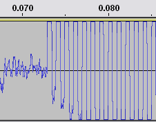 Graphic 1: The AGC is stabilising fairly quickly here. (Audacity Sample)
This Diagram 2 below is showing a stream on 1's as the header. The algorithm is expecting a stream of Data 1's and to begin with, and is looking for any hi to lo transition on the Rx and assuming it is the middle of a Data 1 bit Waveform. After detecting any hi->lo transition it begins to check the subsequent waveform. Graphic 1 is sections A,B&C in Diagram 2.
Diagram 2 illustrates the process of detecting a signal and locking into the data in the packet. From the lefthand side, A is showing static, or noise, and when a signal begins in B the AGC on the 433MHz receiver is stabilizing. Note that early on the program will try to lock onto the negative going edge as shown with the downward black arrow at the start of Phase C. Phase C is the stream of 1's known as the header. Here I have illustrated that receiving fifteen 1's will indicate we have a valid header. Phase D indicates that we have more header bits than we need (this allows for some drift about the AGC starting point). So any excess 1's are then dumped until the bit pattern changes, when at Phase E the bit pattern for 0 arrives. From then on, Phase F (the remainder of the packet, NB not all shown) any number of data bits, 1&0's, can be received. Sometimes the E&F Phase are within the Byte pattern, and sometimes the start bit, E is excluded and it just flags the start, and the bytes begin at Phase F.
How does it know they are properly formed and timed Bit Waveforms? (Please refer to diagram 3 below, NB 7 Bit Waveforms are shown, only alternative ones are labelled). To filter out noise, the input is sampled until a hi->lo event is detected eg at (B) and then again the program re-samples the Rx output about a 1/4 of a Bit Waveform later at (E), to see if it is still lo. If is lo (as the diagram shows) then it is possibly a genuine middle of a 1 Bit Waveform, however if it is not a lo then it was not a genuine hi->lo middle of a 1 Bit Waveform, and the algorithm begins the search for another hi->lo transition all over again. However if this preliminary test is true, it has possibly sampled a midpoint of a 1, so it waits for another half a Bit Waveform (F). This timing is actually 1/4 of the way into the next Bit Waveform, and because we know we are looking for another 1, then the signal should have gone hi by then. If is not hi, then the original sample, that was possibly the mid point of a 1 Bit Waveform is rejected, as overall, it has not followed the 'Bit Waveform rules', and the search (looping) for then next hi->lo transition begins at the start, all over again. Here is a diagram to highlight the previous ideas.
The pink lines are the signal arriving from the 433MHzRx. The long vertical blue lines (eg at A & C) are indicating the start and end of some Bit Waveforms. These are partially covered by the pink signal trace if they coincide. This diagram show 7 bit patterns. B is positioned at the middle of a Bit Waveform, and these are also indicated by the M's. The data contained in each bit pattern is determined by the direction of the transition at M, the middle of the Bit Waveform, and not by what happens at the finish and start of each Bit Waveform.
The Diagram 3 shows the four possible bit sequences, 0->1, 1->0, 1->1, 0->0 and what happens in between each combinations of Bit Waveforms (marked by the orange #1-7 Bit Waveforms).
This simple filtering (delay-check-delay-check etc) allows the program to detect and count the number of successfully detected Data 1's received, and once a minimum has been counted in sequence, then the program can assume it has a valid header coming in. This sampling, by looking for transitions and waiting periods of time to sample, is also applied equally to all subsequent 1's and 0's received and can eliminate badly formed packets if the waveform pattern of the Manchester encoding is not followed (say due to interference or a weak signal). Hence it forms a simple but effective digital filter that greatly reduces spurious results from random or unwanted 433MHz signals.
The transitions at the orange 1-7 do not carry data, but if transitions do occur they are to make sure the subsequent transitions that must occur at the Mid points match the data bit stream correctly (you can think of 1-7 setting up the data transition for the next Mid). The critical aspect of this processing is that this program is always syncing to the Mid point of the Bit Waveform, where the critical data indicating transitions occur. This makes the decoding of the bit stream very tolerant to any errors (data rate wow or flutter in old terms) in sampling the waveforms. This allows the calculations between receiving bits to take different lengths of time (after the middle M of the Bit Waveform) and still not effect the reliability. The delays can be altered plus or minus 15% (or more) and still get reliable reception.
The synchronising 0 bit and may or may not be included in the byte boundaries. Some implementations send a single 0 bit then all the bytes of information, whereas the OS example we are dealing with here just makes sure the first bit in the first byte sent, is always a 0.
Once this "0" is detected then the data stream can be considered synchronised with the detector. This program to decode the Oregon Scientific Weather Station's sensors then decodes a sequence of received bytes that have data encoded in both straight binary and other times, BCD. The number of bytes per packet for each transmitter can also vary. The program must be able to recognise each transmitter early and change the number of subsequent bytes expected for each type. To do this the program begins downloading all bytes (more on that later) and identifies the ID bytes within the first 2 bytes, and when a particular sensor is detected it immediately sets the exact number of bytes expected. So temp/Humidity decoding requires 10 bytes (but only uses 9), Anemometer decoding requires 10 bytes and uses them all, and the Rainfall sensor decoding requires 11 bytes but only needs the four most significant bits of the last byte. If 11 bytes were accepted all the time, the Rainfall would work, but the other two would fail as their signals return to random noise after 10 bytes and this would cause them to be rejected.
Once a data packet is received it is given a checksum check before being declared valid. We now need to diverge, and return back to the way the bits arrive in the data stream and how they are best stored. The easiest way to explain this is to give an example. Let's number the raw Rf incoming bits in order, zero arrives first -
0 1 2 3 4 5 6 7 , and this how it is best to rearrange those bits for OS comptibility
3 2 1 0 7 6 5 4 , so the first bit 0 is actually moved to the fourth position, the next bit 1 is moved to the third position, and so on, and, as this wraps around, all the incoming bits are stored in new positions in a temporary byte, and then stacked into a byte array. It essentially reverses the place values inside each nybble. This properly reflects the environmental values sampled.
Why Oregon Scientific chose this rearrangement is best left up to them to explain, but applying this swapping of positions makes all the data in the stored bytes array so much more logical as well. Binary numbers are found in the correct ascending order etc. Plus when it comes to the Checksum, it is also simpler to calculate as well. Take each 4 bit nybble in the data packet (excluding the checksum byte) and add them up as an 8 bit result. This will result in a byte that can be compared to the last byte in the packet, the checksum byte. The number of nybbles for Temp/Humidity is 16, Anemometer 18, and rainfall 19 (NB rainfall Check Sum byte, is made up of nybbles 20 and 21, ie it bridges the byte boundary).
Once the bits and bytes are stored in this fashion then the checksum becomes trivial, just add up the nybbles and compare to the checksum byte. Reject any packet that does not workout. A simple checksum like this is prone to substitution errors getting through undetected (ie one byte has an error bit, but is balanced out by an inverted error bit in another byte with the same place value. Cyclic redundancy methods for checking data validity are much more robust than the simple arithmetic checksums, but they are not used on the OS Sensors. However by the time the two bytes for the sensor type ID, and the rolling ID code for a particular sensor are put aside, the critical data that changes is down to 5-7 bytes, and probably the checksum for such a small sample is quite acceptable (though if you intend to use any of these sensors for mission critical stuff you may like to disagree with that opinion). Fortunately for me it was easy to program.
Once the bytes for a particular valid packet are stored in the array, they are processed. Some have conversion factors applied, such as binary weighted data for Rain is turned into floating point decimals, and the Anemometer wind speed is converted from metres per second to kilometers per hour. Others such as relative Humidity are provided directly in two BCD characters. Eventually a selection of the numerical data is formatted into ASCII values in a CSV string and sent out via the serial port (over the USB connection). The program has a 1 second interrupt that is used to to send the CSV string every 60 seconds. My Python program on the www server then further processes this string into averages and graphs etc
Before any CSV is sent though, this program checks that it has received a valid sample from each of the three sensors, and only begins sending CSV's when Therm/Hum, Anemometer, UV and Rainfall have all been logged in for valid values. This avoids some values being valid and other being at zero at start up.
This description should give you a good idea of how the OS V3.0 protocol works and how my program tackles decoding that protocol. It is not very sophisticated, when it is all shown now, but was quite a headache to work through originally. The Oregon Scientific Sensors are a good balance of quality engineering, accessible protocols and reasonable price. Really getting a grip on the Manchester protocol was been a major hurdle, but now is well under control. I am hoping my program and this presentation above will help others tackle this protocol in their own projects.
There is now a support Debug Program you can use to develop your own applications in this repository. Edit three values, recipe like, and you could be receiving Manchester encoded bytes in next to no time. Then over to you! Check it out.
I hope you enjoy using them as much as I do, cheers, Rob
Acknowledgements: There are many people, and other publications, I have referenced that have assisted greatly in arriving at this solution and these are listed in the documentation of this program, and explanations given to where they are relevant.
Several features became desirable after the original system had been running for several years. The main concern was a lack of Battery Level indicators and also no direct feedback from the Arduino module of the signals being received. The solution was tackled in two ways, but involving similar parts of the program.
The Battery Levels were a harder one to crack. I checked the WMR86 manual for mention of a battery level indicator and also checked the LCD screen supplied with it for any indicators that referred to battery levels. I could not find any. So I devised this strategy. Should any sensor not be logged within a minute (ie between sending strings of data to the WWW server) then a number is incremented for that Sensor. As soon as that sensor is detected the number is reset to Zero. However if the sensor is not detected for 20 minutes then a flag bit is set for that Sensor. This "detection" number is sent to the WWW server along with all the other data every minute. If it remains 0 then the sensors are OK, if it is non-zero, then it means one of the three sensors have experienced a "continuous down time" of at least 20 minutes. The WWW server can check this and send out an Email at midnight of that day warning of which sensor(s) have been missed. However the warning could arise for a number of reasons, the first obvious one is the batteries are going flat and the second is that something maybe effecting either the transmitter or receiver. Eg the Antenna may have changed position on the Rx and suddenly 2 outof the three are being received. Or maybe some object has been placed bewteen the Tx and Rx and that has knocked out the signal. However, just because the signal drops out it may not be because of the Batteries. The system should be sensitive enough to warn of early stages of battery failure. Even if it begins by small periods of time overnight in the cool night air.
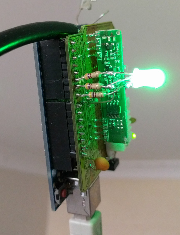
The RGB LED should give a quick indication if an antenna position change for example is still allowing the sensors to be received. An RGB LED was added to the board to indicate which sensor transmitter was detected. By combining Red, Blue and/or Green I could easily produce 8 recognisable states from the LED. Simply observing the board would indicate that the different sensors were being logged. This gave a quick indication, for example after a restart that the Arduino was functioning properly, and so were the 4 Oregon sensors
The version to use these features is MainWeather_09.ino. Please note the order of the sensors in the output string has also been changed. So if you have a system reading this string and processing it from the previous version you will have to alter it as well to use this program as it is.
