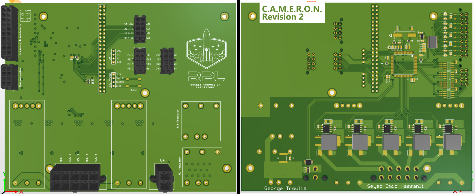
C.A.M.E.R.O.N
The main PCB on Launchy that is responsible for all the Avionics tasks of the rocket
Maintainer
CAMERON is maintained by George Troulis, with numerous contributions from Seyed Omid Hassanli
Naming
C.A.M.E.R.O.N. stands for Changes All Mechanical and Electrical Requirements Over Night. It also happens to be the name of our beloved Chief Engineer, who has done a fantastic job at running RPL and assigning tasks and deadlines to everyone.
Features
CAMERON contains the following features:
- Up to 36V input with 24V, 5V, and 3.3V rails
- Active current-monitoring IC connected to battery input
- BeagleBone Black (Flight Computer)
- Connector for 2 UARTs that connect the FC with XBee Radios
- STM32F4 "RIO" to interface with sensors
- Breakouts for Solenoids, Pressure Transducers, and Thermocouples
- SWD and UART Headers for debugging/programming the STM32F4
- Breakout for separate Recovery PCB that triggers chute at apogee
Todo List for upcoming revisions
- Add indicator LEDs for various items
- Add designators to all components
- Shorten designators for multi-channel elements
- Add Logo and Revision notes on the PCB
- Fix footprint for solder bridge
- Expand the diameter of the holes for the BeagleBone
- Make annular rings for Molex connectors larger
- FIX THE MOSFET FOOTPRINT (Gate and Drain are flipped)
- Add thermal relief to pads
- Add silk to the XBee connector and remove the J8 designator
- FLIP BOOT PINS (test them first)
- Move the "5V Regulator" Label away from the stitching vias
- Add tenting to the stitching vias next to the power connector
- Distribute silk designators on Generic GPIO breakout
- Make copper pours reach the edges of the PCB
- Add Silk designators to the TC/PT breakouts (PT1, TC1 etc)
- Flip the flipped designators
- Label 3V3 on the SWD Header
-
Add Reset signal to Programming header(Not necessary)
