I wanted to gain a better understanding of the power consumption of my hoverboard during different riding situations. For that reason, I built a hoverboard power monitor, which is a power meter and data logger. The device measures Amperes and Voltage and calculates the current power consumption in Watts. The measurements are shown as numbers and as oscillograms on a little TFT display. They can also be logged on a SD-card with a temporal resolution of about 10Hz. A built-in real-time clock makes it easy to match the data with a video clip of the ride.
The power monitor is plugged in between battery and hoverboard electronics with its XT60 connectors. It is itself powered by the hoverboard battery. Besides recording the power consumption of hoverboard or scooter rides, the device can also record the charging process, e.g. if you want to plot charging curves.
The hoverboard power monitor is built around an Arduino Nano and it is programmed with the Arduino IDE 1.8.11.
I've also programmed a visualizer in Processing 3.5.4. This program reads logfiles and creates a timing-correct sequence of png's, which can be superimposed onto a video clip. The program also calculates the Ampere hours of the logging duration.
 Here's a longer version of the video above
The hardware consists mainly of modules which I slapped together on a perfboard. Here's the parts list:
- Arduino Nano (clone)
- DS1307 Realtime clock
- 1.8" SPI TFT 128x160 (KMR-1.8 SPI) TFT display with SD card slot
- ACS 712 Hall effect Ampere meter
- XL7015 DC step down converter
- 10A Fuse + fuse mount
- 5 x 1K Resistors
- 4 x 2K Resistors
- 1 x 10K Resistor
- 1 x 22 Ohm Resistor
- 3 Buttons
- 1 Piezo speaker
- 1 Big capacitor (I used a 1F 5.5V, which is overkill - but it was smiling at me when I looked into the capacitors box)
- XT60 connectors
- Perfboard
Let's have a look at the schematic above:
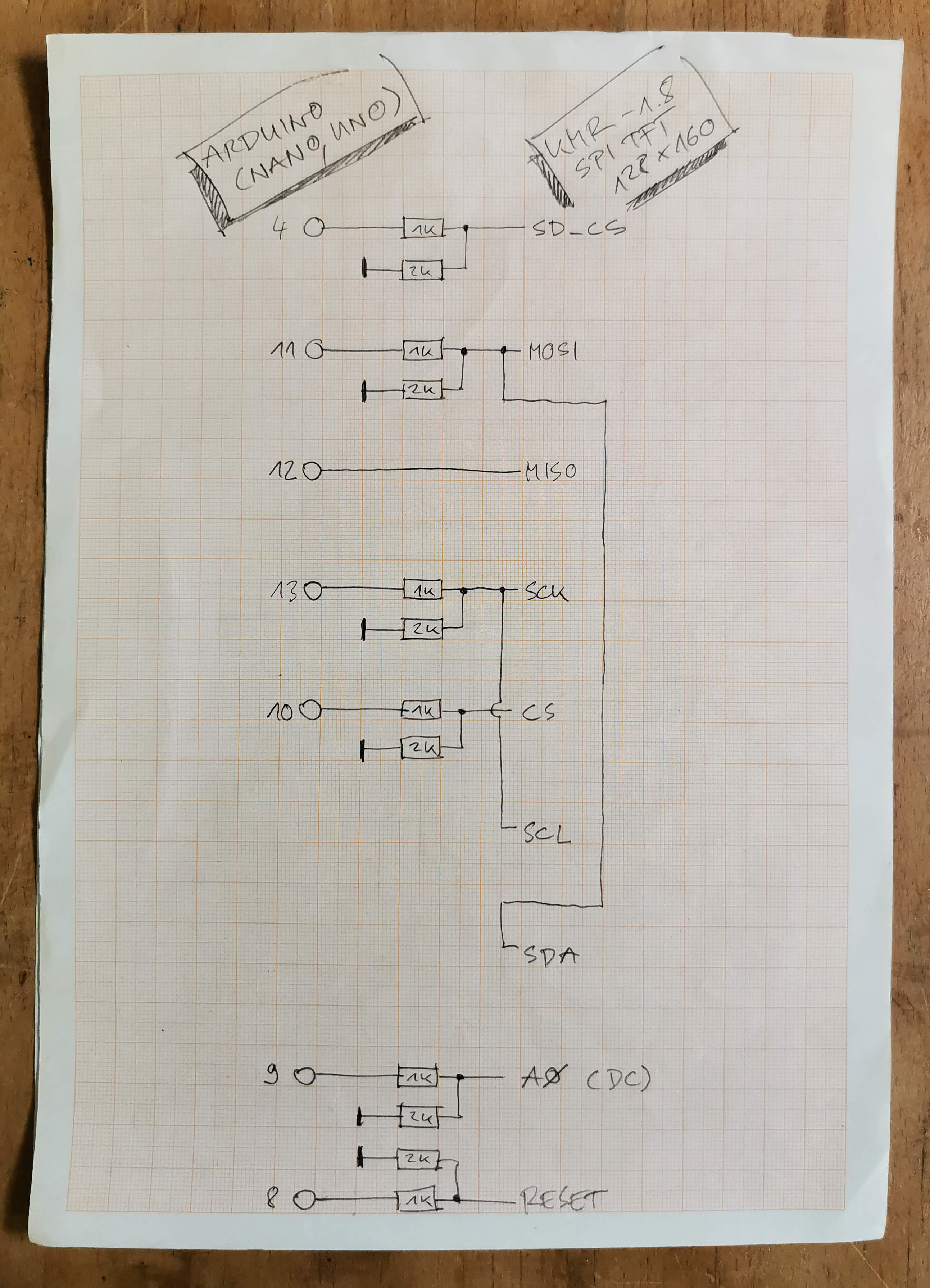
EDIT: There are some connections between Arduino and display missing in the drawing above. The reason is that I built the circuit board a while ago without documenting it properly (bad idea!) and then I reverse engineered the drawing (while it seems I forgot a few things!). Below is a correct table and an updated schematic for the data connection between the KMR1.8 display and the Arduino
| Display | Arduino |
|---|---|
| SD_CS | Pin 4 |
| MOSI | Pin 11 |
| MISO | Pin 12 |
| SCK | Pin 13 |
| CS | Pin 10 |
| SCL | Pin 13 |
| SDA | Pin 11 |
| A0 | Pin 9 |
| RESET | Pin 8 |
The Arduino uses a different logic voltage than the display. Therefore, all the signals from the Arduino to the display go through a voltage divider, made of 1K and 2K resistors. The additional 22 Ohm resistor at the display is there to protect the LED's of the backglight.
The Arduino senses the battery voltage via a 1:10 voltage divider on pin A1. The Amperes are sensed via an analog voltage on pin A0.
For building the case, I used some Forex (PVC foam board). This can be easily cut with a utility knife and the flat pieces are all held together with zip ties. This goes faster than 3D printing and if you drop the thing, it doesn't break.


