Latest updates, more precise pixel clock and offset, see pico228MHz_VpolCore1 branch.
Simple TTL (MDA/CGA/EGA) to VGA converter based on RPi Pico.
VGA output is 720x400 (-31.4kHz/+70Hz).
Input video modes:
| mode | resolution | frequency / polarity | pixel clock | VSYNC | total lines |
|---|---|---|---|---|---|
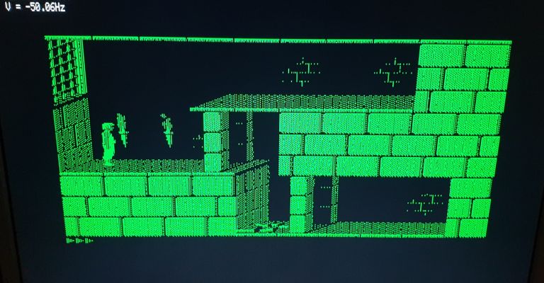
| MDA | 720x350 | H:+18.4kHz V:-50Hz | 16.257MHz | 16 lines | 369 |
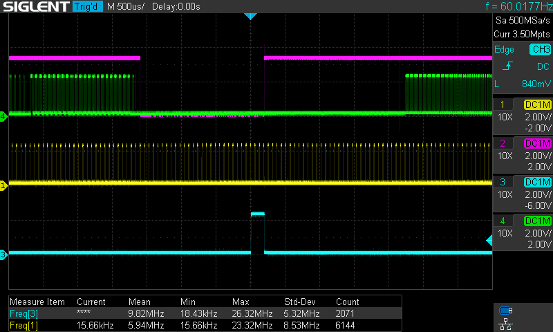
| CGA | 640x200 | H:+15.7kHz V:+60Hz | 14.318MHz | 3 lines | 262 |
| EGA Mode 1 | 640x200 | H:+15.7kHz V:+60Hz | 14.318MHz | 3 lines | 262 |
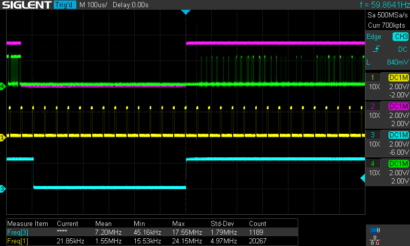
| EGA Mode 2 | 640x350 | H:+21.8kHz V:-60Hz | 16.257MHz | 13 lines | 364 |
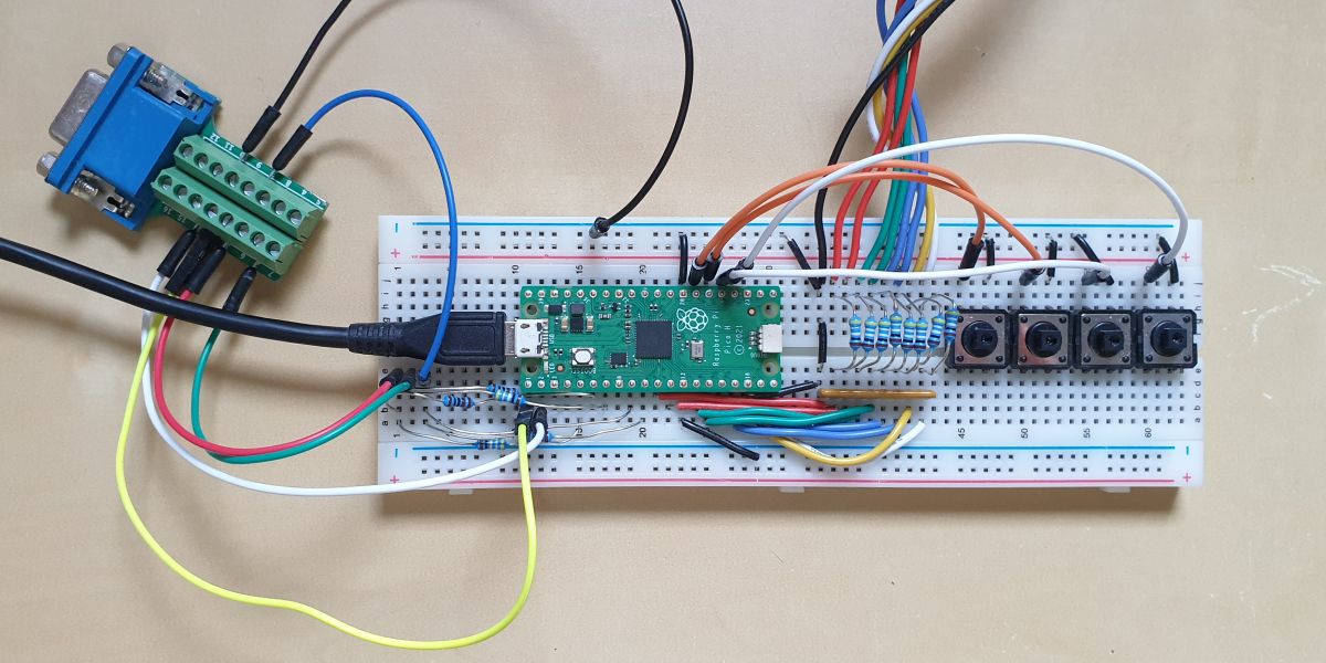
Using the buttons, the pixel clock (horizontal width) can be adjusted. In MDA and CGA/EGA the pallete can be toggled (GP21).
Tested only with OAK067 and ET3000 EGA/VGA graphics cards.
RPi Pico (RP2040)
11
11
- optional
2$\times$ 100 Ω resistors
DB9 male connector
DB15 female connector
4 buttons
1nF capacitor (optional, if VSYNC is noisy)
cd src
# (copy pico_sdk_import.cmake from the SDK)
mkdir build && cd build
cmake .. -DPICO_SDK_PATH=<path_to_pico_sdk>
make
If Pico 2 (SDK 2.0) is the target, add -DPICO_BOARD=pico2 to cmake, i.e.
cmake .. -DPICO_SDK_PATH=<path_to_pico_sdk> -DPICO_BOARD=pico2
cf. https://vanhunteradams.com/Pico/VGA/VGA.html
-
Use at your own risk! Don't expect too much.
-
The 114 MHz system clock reduces jitter in the VGA output.
The input pixel clock will probably introduce jitter. The clock divider for the pixel clock can be adjusted (GP20/19). The parameters can be displayed (GP18). -
If scanning starts too early, the last line would be missing. For normal use, a frame buffer of 720x351 (or 724x351) is recommended (see below). Once the best settings have been found, they can be set in
ttl_in.h, e.g.ttlmode_t mode_MDA { .div_int = 1, .div_frac = 232 } ttlmode_t mode_EGA2 { .div_int = 1, .div_frac = 207 } ttlmode_t mode_CGAEGA { .div_int = 2, .div_frac = 77 }
(can be adjusted using
BUTTON_PLS/BUTTON_MIN)
For OAK067,ttlmode_t mode_CGAEGA { .div_int = 2, .div_frac = 3 } // 14.167MHz
shows no jitter, however the scan line is too long at this frequency. (test branch: back porch/horizontal scan offset.)
For precise adjustments of pixel clock and offset a higher system frequency (228 MHz) is needed, cf. pico228MHz (no or minimal jitter on OAK067). It also helps converting to CGA palette. On ET3000 vmode detection sometimes fails, so checkout pico228MHz_VpolCore1.
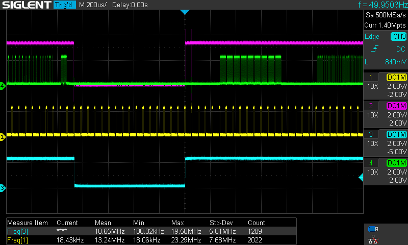
In EGA Mode 2 there should be 350 visible lines, 13 lines vertical sync, and 364 total lines, i.e. not much room for front/back porch.
640x350 EGA Mode 2:
640x200 CGA/EGA:
720x350 MDA:
-
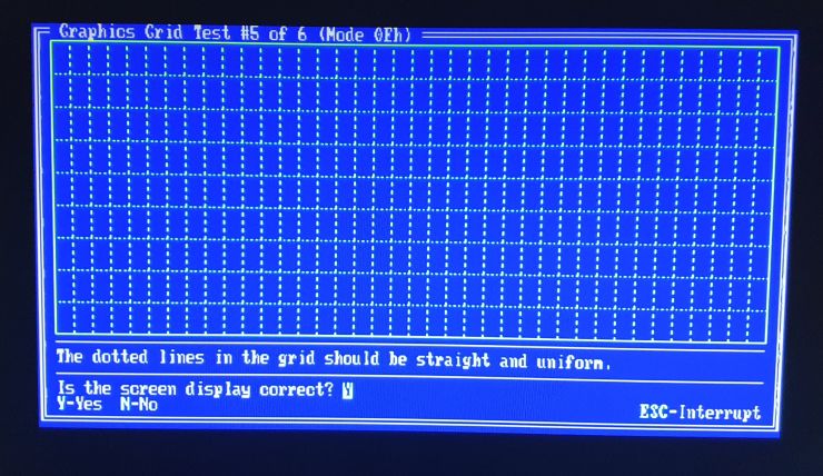
Use test images (e.g. CheckIt) to find the right pixel clocks.
640x200 EGA:
640x350 EGA Mode 2:
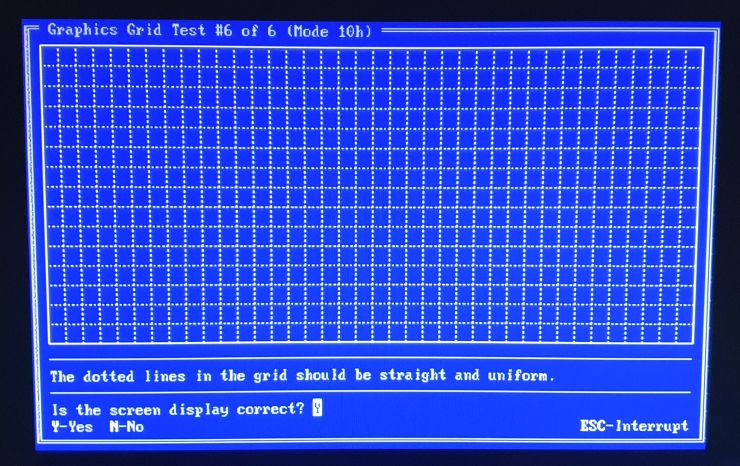
(The distortion is due to the camera angle.) -
If USB output is enabled, the clock divider fractional part for the current video mode can be seen in a serial monitor. However, if
pico_enable_stdio_usb(ttl2vga 1)is enabled, the frame buffer is limited to 720x350 (or 724x349). Ifpico_enable_stdio_usb(ttl2vga 0)is disabled,vga_out.h:YACTIVEandttl_in.h:YLNS_MDAshould be set to 351 lines. This would take into account variations between different graphics cards. -
VGA 720x400@70Hz (-31.4kHz/+70Hz):
Some monitors might output 640x400, thus MDA scan pixel clock of 16Mhz can be reduced to 8/9*16Mhz=14MHz usingBUTTON_PALor by settingttlmode_t mode_MDA { .xscanlrd = 720 }
to
ttlmode_t mode_MDA { .xscanlrd = 640 }
