This document outlines the DECstation 2040, a RP2040 based DECstation 3000 emulator that can run DECWindows. A summary of features:
Hardware:
- RP2040, running at 1.8v/300 MHz
- 32 MB of PSRAM
- 8 MB SPI flash
- uSD card socket
- Monochrome VGA at 1024 x 864
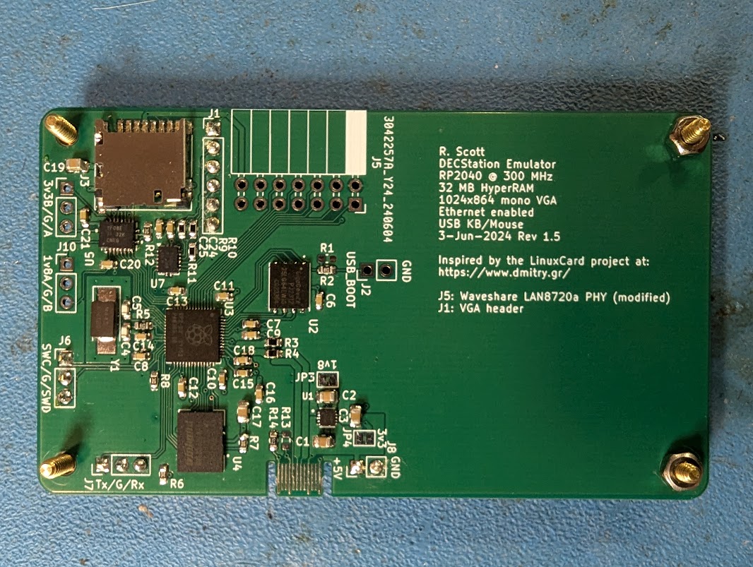
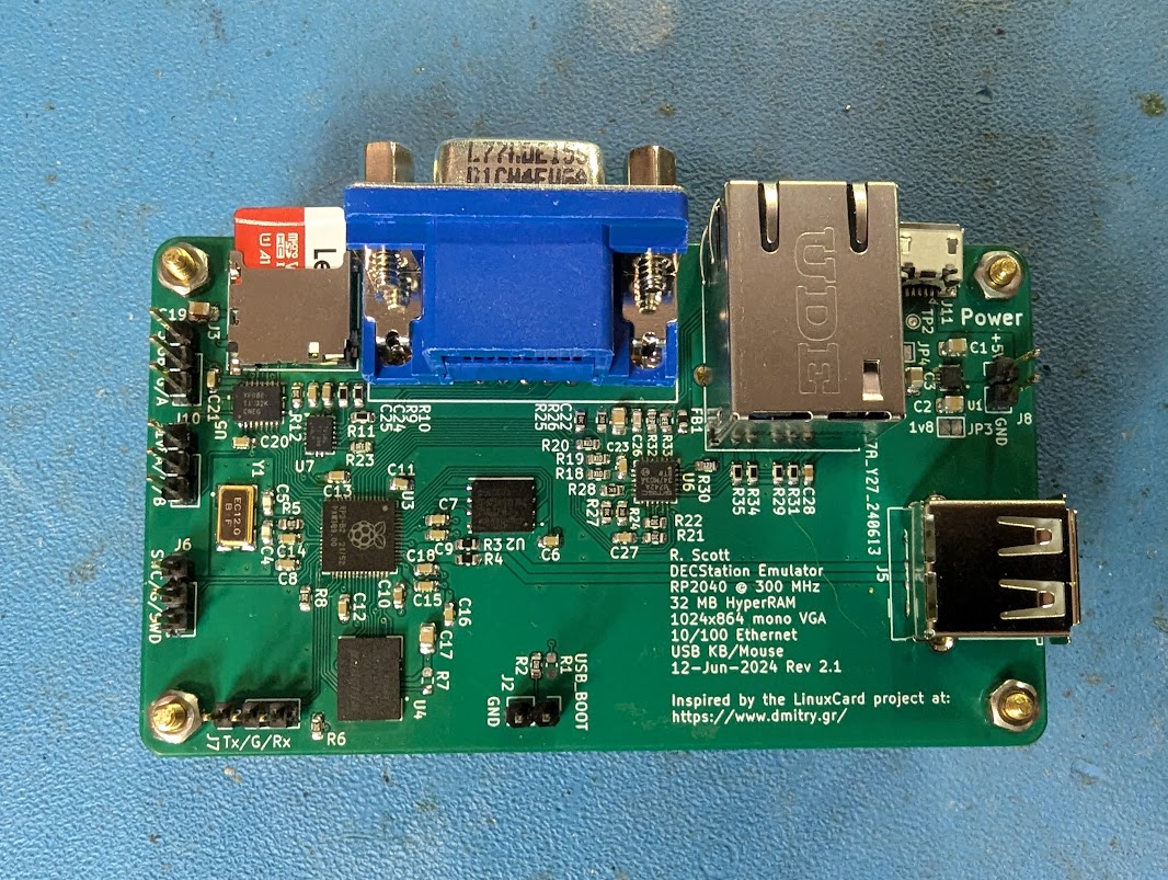
- Ethernet RMII PHY support (socket on rev 1.5, integrated in rev 2.1)
Software:
- 4 port PSRAM PIO engine
- PIO driven VGA, with seperate 16x16 cursor plane overlay
- USB HID to DECWindows keyboard and mouse
The PSRAM/HyperRAM PIO engine provides 42/32 MB/s (write/read) of memory bandwidth. Further, four PIO engines are used to provide four seperate read/write memory ports. This allows independent memory access for the emulated CPU, video DMA, and receive/send Ethernet traffic. Note that all 32 instruction slots are used.
The video PIO engine can support up to a sysclk/2 pixel rate. Thus, for the 300 MHz sysclk typically used, it is possible to run 1080p60 at a pixel rate of 148.5 MHz. The default video rate is 1024 x 768 @ 70Hz, as this matches the screen used for development and the pixel rate is an integral divisor from sysclk. Only five PIO instruction slots are used.
To drive the video PIO engine, five DMA channels are used. They are allocated as follows:
- ctrl_dma_chan - points to DMA channel command packets
- data_dma_chan - executes DMA command packets
- ps_read_chan - points to PSRAM read data buffer
- inc_dma_chan - used to generate loop counter indices
- cur_inc_dma_chan - used as cursor loop counter
This project uses the RP2040 DMA sniffer to dynamically generate PSRAM addresses, which eliminates the need to have a per-line PSRAM command packet. Further, it uses the inc_dma_chan to enable DMA command loops, eliminating per-line DMA commands needed to send commands to the PIO pixel and PSRAM PIO engines. This makes the amount of memory needed to drive video independent of the display format. Currently, 86 DMA command packets are used vs. approximately 2250 required for 1080p if a per-line DMA structure was used.
In order to eliminate the latency from when the PSRAM PIO engine FIFO has read data, and its delivery to SRAM, we use the ps_read_chan. This channel is chained to after a PSRAM DMA command is executed. Without this channel, the PSRAM PIO engine FIFO would be not be emptied until the next DMA command is executed. This impacts the non-video PSRAM channels, as they must wait unitl the video PSRAM command is complete.
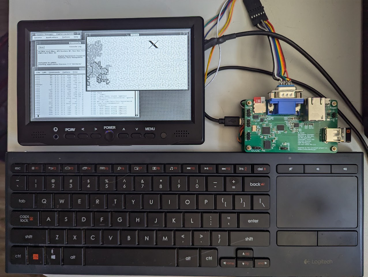
The USB HID code supports (at least) two keyboard/mouse combo types: Rii mini X1 (model: RT-MWK01), purchased at MicroCenter, and Logitech K830.
Dmitry's code at http://dmitry.gr/?r=05.Projects&proj=33.%20LinuxCard was modified to support the RP2040, as well as adding support for video and USB mouse/keyboard input. With overclocking and running the assembly language version of the CPU emulator, Dmitry's Linux image reports a BOGOMIPS rating of 13.44.
Build either rev 1.5 or 2.1, using the appropriate emu_brd directory. Please note that rev 2.1 is still undergoing Ethernet debug, and has exhibited significant packet drops. I use JLCPCB for board fabrication, and there are Digikey BOM spreadsheets in doc/bom. Recommend building two boards: one to use as a 1.8v CMSIS debugger, and the other as the target. Feel free to only populate the RP2040 related components on the CMSIS debugger.
The surface mount parts aren't too troublesome - I find the PSRAM BGA to be much easier to solder than the RP2040 QFN. My technique is to use a hot-air SMT rework tool. Recommended assembly steps:
- Solder the voltage regulator, check for 1.8v and 3.3v when done.
- Solder all of the passives, the RP2040, flash, and the USB connectors if building rev 2.1. (Note that two bodge wires are needed to connect J5 and J11 D+/D- as my assumption that USB-A could serve as non-host connector was incorrect). When done, use blink_bringup (below) to check connections. (Edit blink.c to enable the pins to check).
- Solder the HyperRAM chip, run mem_test to check connections.
- Solder the voltage translator chips, edit blink.c and run to check connections.
- Solder the connectors.
For rev 1.5: Needs modified waveshare LAN8722 board. In addition to the modifications outlined at: https://github.com/maximeborges/pico-rmii-ethernet, pin 13 of the 7 x 2 connector (originally NC) is used as VDDIO for the LAN8722 chip. To make this modification, cut the existing connection between LAN8722 pin 9 to 3.3v, and route pin 9 to pin 13 of the connector. This allows the use of 1.8v I/O from the DECstation 2040 board. Also needed is a 6 pin header to VGA connector. See rev 2.1 schematic for VGA pins needed.
Start with: http://dmitry.gr/?r=05.Projects&proj=33.%20LinuxCard Download the images, particularly the ultrix.gui image. This should be placed on a FAT32 for uMIPS. Edit uc_main.c to select which image to run.
Next, go to where this README.md is stored. Then set current directory to sw. Edit the "source_this" file to reflect the location of the Pico SDK, and source this file to set the PICO_SDK environment variable for the current session.
A good place to start is with the blink_bringup directory. CD to this, and do:
cmake -B build -S .
Build software via
./build.sh
This will generate an .elf file in build/src. Use picotool to load this onto the target board. After rebooting, should get "hello, world" on USB serial, as well as on the hardware serial port. A 500 Hz square wave should be present on GPIO21 (ret_clk). This can be changed via editing the src/blink.c file. I use this tool incrementally while soldering the board, to verify connectivity.
Next, build the CMSIS debugger. CD to the picoprobe directory and build with:
cmake -B build -DCUSTOMPROBE=1 make -C build
Program with
sudo picotool load build/customprobe.elf
Now go to the psram directory and do:
cmake -B build -S .
Build software via
./build.sh
This will generate most of the available packages. Of interest are:
- mem_test - a simple memory tester
- fb_test - test program for the frame buffer library
- fb_mem_test - memory test with frame buffer enabled
- pico-rv32ima - RISC-V linux emulation
- uMIPS - DECstation emulation
- pico_rmii_ethernet_httpd - test program for RMII.
There are shell scripts to load the above:
- cl_sram.sh - sd command line
- eth_sram.sh - ethernet test
- fb_flash.sh - framebuffer library test, run from flash
- fb_sram.sh - framebuffer library test, run from SRAM
- fbm_flash.sh - memory test with framebuffer enabled, run from flash
- fbm_sram.sh - memory test with framebuffer enabled, run from SRAM
- mt_sram.sh - memory test, run from SRAM
- mt_flash.sh - memory test, run from flash
- um_flash.sh - uMIPS emulator, run from flash
- um_sram.sh - uMIPS emulator, run from SRAM
Running the code: Connect the debugger board to the SWD port on the target. Start the CMSIS debugger via sw/start_cmsis.sh. Execute one of the scripts above. This will load the program into RP2040 SRAM and start it.
If you wish to run from flash, comment out the no_flash line in the source CMakeLists.txt. Note that the uMIPS emulator requires "copy_to_ram" to be enabled when running from flash.
This project has been a voyage of discovery. The first doc/build_log.txt entry was on 23-mar-2023, but I'd been thinking of building a business card ever since I'd read Dmitry's LinuxCard web page. I've learned how to use the RP2040 PIO engines and the DMA subsystem to push pixels. I'm amazed at how flexible and capable the RP2040 has turned out to be. Hats off to the RP2040 designers!
Most enjoyable moments:
- When the PSRAM PIO engine finally ran the memory test overnight.
- When the second solution to the problem of how to get the DMA subsytem to do a counted loop actually worked without killing SD card access.
- When the DMA cursor read data during blanking worked, giving smooth cursor movement.
Less than enjoyable moments:
- Realizing the "optimization" of reordering data on the PSRAM to improve layout was wrong, after submitting the design to JLCPCB.
- Realizing that the first flash part chosen didn't support "Continuous Read Mode". On the other hand, this did force me to learn how to do SRAM builds, speeding up development.
- Having the wrong footprint for the level translator on rev 1.3.
- Finding out that Digikey no longer stocked the Ethernet connector on rev 2.0, after submitting PCB. Related - the PSRAM was out of stock, so clicked on the recommended alternative. Was disappointed when the box showed up, and it was the waferscale part. Tiny, but unsolderable.
- Use the ps_get_buf DMA subroutine to setup the cursor PSRAM command. This will reduce the memory footprint.
- Write the lance Ethernet emulation code for uMIPS.
- Port MicroMac https://axio.ms/projects/2024/06/16/MicroMac.html
This project would not exist without Dmitry's excellent LinuxCard project, at: http://dmitry.gr/?r=05.Projects&proj=33.%20LinuxCard
Inspiration and software framework: https://github.com/Wren6991/PicoDVI.git
DEC mouse and keyboard support used code from: https://hackaday.io/project/19576-dec-mouse-adapter and https://github.com/pkoning2/lk201emu.git
Ethernet: https://github.com/maximeborges/pico-rmii-ethernet
Also, Hackaday.com for articles on SMT soldering, USB-C, etc., giving me confidence that I could actually do this project!
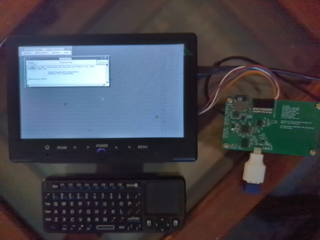
A selection of pictures from doc/photos follows. See doc/photos for pictures of previous versions and how the emulated video output progressed from first pixel to current.
Video showing Xmaze/worms running
Rev 1.5
Rev 1.5 running
Rev 2.1
Rev 2.1 running with Logitech keyboard
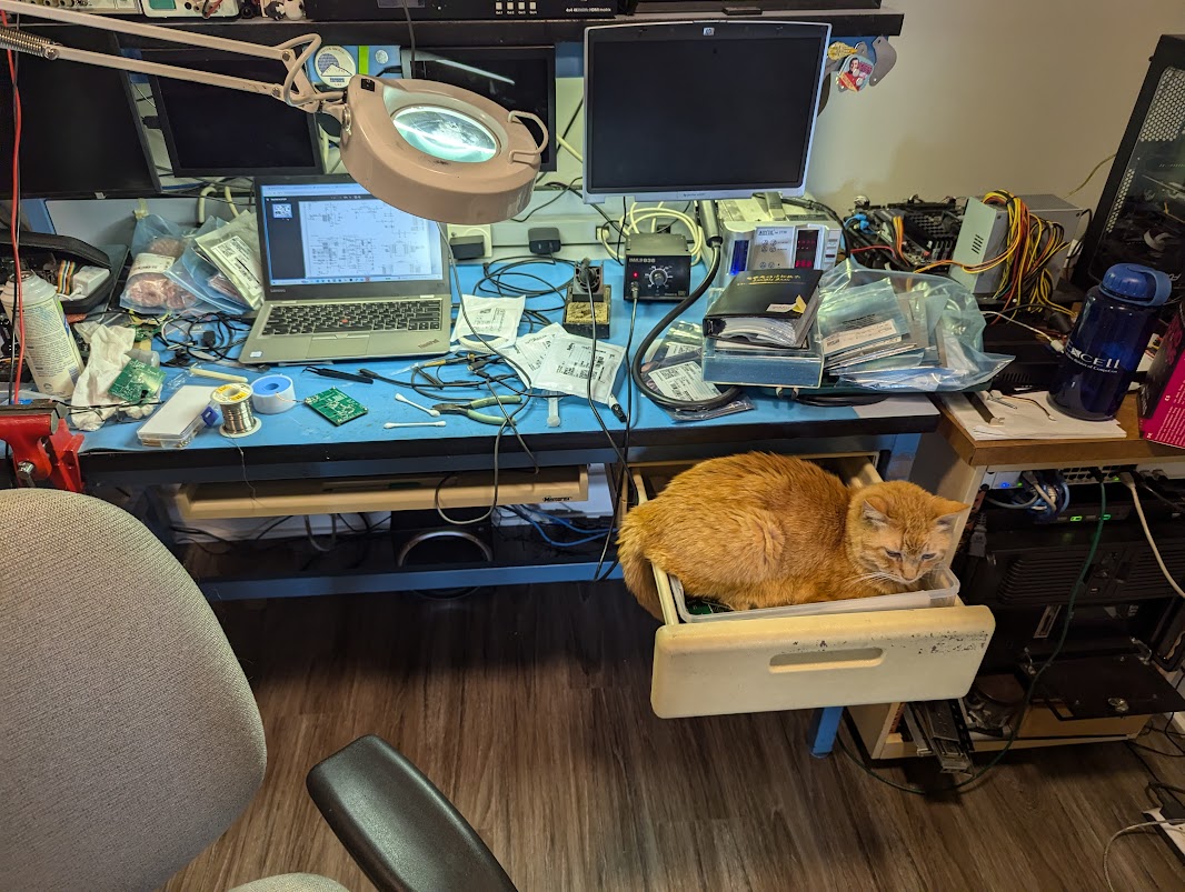
Helper cat in the parts box
