This ESP8266 firmware implements the SWIM protocol for debug access / flashing of STM8 devices.
The STM8 SWIM protocol is well documented in UM0470. Communication runs @8MHz, as such the ESP (running at 80MHz) is well-suited for bit-banging this protocol and leaves enough computing capacity for implementing this without paying too much attention to instruction cpu cycles.
I built this, because I was debugging a chip, clocked by a slow external clock. Since debug access is based on the cpu’s clock rate, the SWIM module was too slow to respond for the stlink device I had used before. Taking a look at my logic analyzer I saw that the microcontroller indeed sent a response, but I was unable to get it out. Also I really don't see the point of needing a special one-purpose-only device to flash the stm8 chips (even though they are cheap).
The timing is based on counting cpu-cycles, as such the code currently only works if the ESP is running at 80MHz and not at 160MHz. Only slow data transfer speed is implemented, but this shouldn’t really matter. From what my logic analyzer told me the actual stlink device didn’t use high-speed either.
- Install esp-open-sdk
sudo apt install esptool- Compile and flash
ESP_OPEN_SDK=/opt/esp-open-sdk
export XTENSA_TOOLS_ROOT=$ESP_OPEN_SDK/xtensa-lx106-elf/bin SDK_BASE=$ESP_OPEN_SDK/sdk flash
make flash
Grap the latest esp-stlink-firmware.tgz from the releases page and flash it using:
esptool --baud 460800 --port /dev/ttyUSB0 write_flash \
    0x00000 firmware/0x00000.bin \
    0x10000 firmware/0x10000.bin

-
The STM8 device of course needs G and 3.3V connections.
-
The RST line is connected to ESP8266 GPIO5 (D1 on NodeMCU).
-
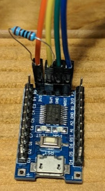
SWIM is connected to ESP8266 GPIO4 (e.g. D2 on NodeMCU) via a 1kΩ pull-up resistor (this is important since the builtin pullup resistor is not capable of pulling up the line fast enough!).
NOTE: You can likely just integrate the resistor into your wires (see the attached picture) or even solder it to your ESP-board permanently.

To use other pins (e.g. on ESP01), edit src/driver/swim.h.
The ESP exposes a serial interface which stm8flash uses to communicate with
the ESP. Typically you’ll want to use a USB-to-serial adapter.
The internet is full of tutorials on how to connect to an ESP.
If you like it simple, get a NodeMCU or WeMos development board. These work
out of the box, just connect to your computer’s USB, make flash and you’re
ready to use stm8flash with espstlink.
You need to build libespstlink.so first by running:
make -C lib
Easiest is to use the python tool (only works with STM8S not STM8L for now):
python3 python/flash.py -d /dev/ttyUSB0 -i sample.ihx
Note: Older versions of stm8flash will not work with current versions, since starting with v0.2 of espstlink the default baudrate was switched from 115200 to 921600, which allows for significantly faster flash speeds.
Grab stm8flash from https://github.com/rumpeltux/stm8flash.
stm8flash -c espstlink -p stm8s103f3 -w sample.ihx
So far this has only been tested with an stm8s103f3 chip. It’s likely that other devices work as well, but since there may be issues regarding timing of the wire protocol, there’s no guarantee that it’ll work.
stm8spi is a related implementation (ab)using the raspberry PI’s SPI to perform SWIM communication. However, due to relying on SPI and its timing, it's severly limited and wouldn't work for my use-case either.