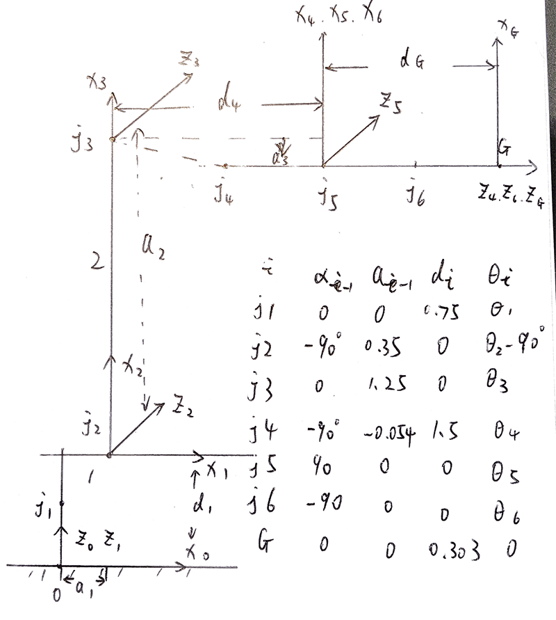
1. Run the forward_kinematics demo and evaluate the kr210.urdf.xacro file to perform kinematic analysis of Kuka KR210 robot and derive its DH parameters.
I followed the lesson materials to analyze KR210 schematic and then made following DH parameters.
Put the DH patameters in a table.
| i | alpha(i-1) | a(i-1) | d(i) | theta(i) |
|---|---|---|---|---|
| 1 | 0 | 0 | 0.75 | q1 |
| 2 | - pi/2 | 0.35 | 0 | q2-pi/2 |
| 3 | 0 | 1.25 | 0 | q3 |
| 4 | -pi/2 | -0.054 | 1.5 | q4 |
| 5 | pi/2 | 0 | 0 | q5 |
| 6 | -pi/2 | 0 | 0 | q6 |
| G | 0 | 0 | 0.303 | 0 |
2. Using the DH parameter table you derived earlier, create individual transformation matrices about each joint. In addition, also generate a generalized homogeneous transform between base_link and gripper_link using only end-effector(gripper) pose.
I defined the transformation matrix as follows,
def dh_matrix(q, a, d, alpha):
    return Matrix([[cos(q), -sin(q), 0, a],
                   [sin(q) * cos(alpha), cos(q) * cos(alpha), -sin(alpha), -sin(alpha) * d],
                   [sin(q) * sin(alpha), cos(q) * sin(alpha), cos(alpha), cos(alpha) * d],
                   [0, 0, 0, 1]])
Then transformation matrices for individual joint are,
T0_1 = dh_matrix(q1, a0, d1, alpha0)
Matrix([
[cos(q1), -sin(q1), 0,    0],
[sin(q1),  cos(q1), 0,    0],
[      0,        0, 1, 0.75],
[      0,        0, 0,    1]])
T1_2 = dh_matrix(q2 - pi / 2, a1, d2, alpha1)Matrix([
[sin(q2), cos(q2), 0, 0.35],
[ 0, 0, 1, 0],
[cos(q2), -sin(q2), 0, 0],
[ 0, 0, 0, 1]])T2_3 = dh_matrix(q3, a2, d3, alpha2)
Matrix([
[cos(q3), -sin(q3), 0, 1.25],
[sin(q3), cos(q3), 0, 0],
[ 0, 0, 1, 0],
[ 0, 0, 0, 1]])T3_4 = dh_matrix(q4, a3, d4, alpha3)
Matrix([
[ cos(q4), -sin(q4), 0, -0.054],
[ 0, 0, 1, 1.5],
[-sin(q4), -cos(q4), 0, 0],
[ 0, 0, 0, 1]])T4_5 = dh_matrix(q5, a4, d5, alpha4)
Matrix([
[cos(q5), -sin(q5), 0, 0],
[ 0, 0, -1, 0],
[sin(q5), cos(q5), 0, 0],
[ 0, 0, 0, 1]])T5_6 = dh_matrix(q6, a5, d6, alpha5)Matrix([
[ cos(q6), -sin(q6), 0, 0],
[ 0, 0, 1, 0],
[-sin(q6), -cos(q6), 0, 0],
[ 0, 0, 0, 1]])T6_G = dh_matrix(q7, a6, d7, alpha6)Matrix([
[cos(q7), -sin(q7), 0, 0],
[sin(q7), cos(q7), 0, 0],
[ 0, 0, 1, 0.303],
[ 0, 0, 0, 1]])And the homogeneous transform from base_link to gripper_link is a post-product of individual transformation defined above,
T0_G = T0_1 * T1_2 * T2_3 * T3_4 * T4_5 * T5_6 * T6_G3. Decouple Inverse Kinematics problem into Inverse Position Kinematics and inverse Orientation Kinematics; doing so derive the equations to calculate all individual joint angles.
The last three joints of Kuka KR210 is a spherical wrist and their axes intersect at the origin of joint5. The problem to obtain wrist center therefore is to calculate the position of joint5. Given the end-effector's position (px, py, pz) and orientation (roll, pitch, yaw), we have its homogeneous transformation matrix Rrpy, which is the same as R0_6. So I calculated wrist center wc through,
wc = EE - (d6 + d7) * Rrpy[:3, 2]
xc = wc[0]
yc = wc[1]
zc = wc[2]
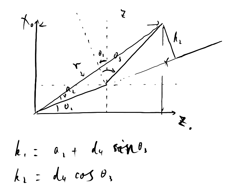
For solving Inverse Position Kinematics, namely theta1, theta2 and theta3, is the most difficult part in this project, especially theta2 and theta3. First, I use x and y value of wc to get theta1,
theta1 = atan2(yc, xc)To calculate theta2 and theta3, I found it's easier for me to derive them through trigonometry formulas by projecting wrist center onto the X-Z plane.
Let's define x = xc - a1, z = zc - d1 offset = -atan2(a3, d4) and t = sqrt(a3**2 + d4**2), because,
x = a2 * sin(theta2) + t * cos(theta2 + (theta3_dot))
z = a2 * cos(theta2) - t * sin(theta2 + (theta3_dot))
x**2 + z**2 = a2**2 + t**2 - 2 * a2 * t * sin(theta3_dot))
So,
cos(theta3_dot) = sqrt(1 - sin(theta3_dot)**2)
k1 = a2 - t * sin(theta3_dot)
k2 = t * cos(theta3_dot)
theta3 = atan2(sin(theta3_dot), cos(theta3_dot)) - offset
theta2 = atan2(x, z) - atan2(k2, k1)
Since I solved Inverse Position Kinematics by now, it's not too hard to derive theta4, theta5 and theta6. Because R0_6 is equal to Rrpy,
R0_3.transpose() * R0_6 = R0_3.transpose() * Rrpy = R3_6And R3_6 is a homogeneous transformation about theta4, theta5 and theta6 in the following form,
[-sin(q4)*sin(q6) + cos(q4)*cos(q5)*cos(q6), -sin(q4)*cos(q6) - sin(q6)*cos(q4)*cos(q5), -sin(q5)*cos(q4)],
[sin(q5)*cos(q6),                            -sin(q5)*sin(q6),                           cos(q5)],
[-sin(q4)*cos(q5)*cos(q6) - sin(q6)*cos(q4),  sin(q4)*sin(q6)*cos(q5) - cos(q4)*cos(q6), sin(q4)*sin(q5)]
then,
theta4 = atan2(sin(q4), cos(q4)) = atan2(R3_6[2, 2], -R3_6[0, 2])
theta5 = atan2(sin(q5), cos(q5)) = atan2(sqrt(R3_6[0, 2] * R3_6[0, 2] + R3_6[2, 2] * R3_6[2, 2]), R3_6[1, 2])
theta6 = atan2(sin(q6), cos(q6)) = atan2(-R3_6[1, 1], R3_6[1, 0])1. Fill in the IK_server.py file with properly commented python code for calculating Inverse Kinematics based on previously performed Kinematic Analysis. Your code must guide the robot to successfully complete 8/10 pick and place cycles.
After filling in IK code mentioned above in IK_server.py, I tried 12 pick & place and the robot succeeded in all cycles.
Although my current code works fine in the pick and place cycles, it takes quite a few seconds in calculating all Inverse Kinematics for the given waypoints (about 0.5s of each). It's quite slow in my reckoning and I'd like to improve the performance given the chance to pursue this project in the future, maybe through c++.


