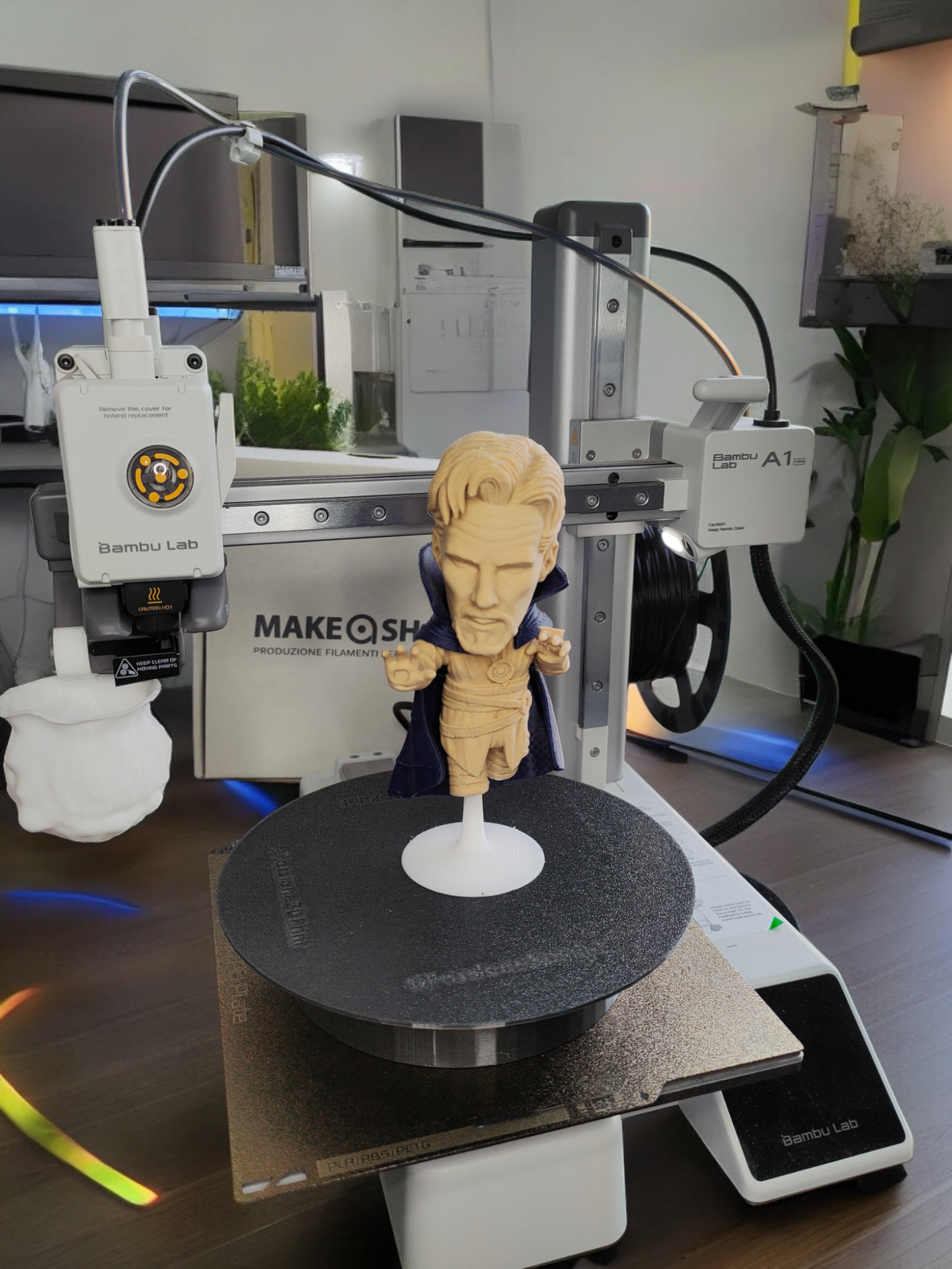
Welcome to the DIY 3D Printed Rotating Display Table project! This guide will take you through the steps to create your very own rotating display table, perfect for showcasing 3D printed models, collectibles, or products. We'll cover everything from gathering supplies, 3D printing parts, programming the Arduino, and assembling the final product. Let's get started!
- Introduction
- Supplies
- Step 1: 3D Print the Components
- Step 2: Upload the Arduino Code
- Step 3: Assembling the Display Table
The DIY 3D Printed Rotating Display Table is an excellent project for hobbyists, makers, and professionals alike. Using 3D printing and basic electronics, you can create a customizable display table that brings motion and style to your presentations.
- Arduino Nano: Microcontroller to control the stepper motor.
- 28BYJ-48 Stepper Motor with ULN2003 Driver: Provides precise control for smooth rotation.
- DC Power Plug: Powers the Arduino Nano and the stepper motor.
- PLA Filament: Ideal for strength and ease of use.
- 3D Printer: Capable of printing with fine details.
- Jumper Wires: For connections between components.
- Screwdriver Set: For assembly.
- Hot Glue Gun or Super Glue: Optional, for securing parts.
- Breadboard: Optional, for initial testing.
- Power Supply: Compatible with the DC power plug and Arduino Nano.
First, 3D print all necessary components using your modeled parts. Ensure your printer is properly calibrated, and use the following settings for optimal results:
- Layer Height: 0.2 mm
- Wall Thickness: 1.2 mm
- Infill Density: 20-30%
- Prepare Your 3D Printer: Check bed leveling, clean the extruder, and load the filament.
- Load the 3D Models: Import your parts into slicing software.
- Configure Print Settings: Adjust settings for quality and strength.
- Slice the Model: Generate the G-code for your 3D printer.
- Start Printing: Print each component, monitoring the first few layers for adhesion.
Next, program the Arduino Nano to control the stepper motor. Follow these steps:
- Install Arduino IDE: Download from here.
- Connect the Arduino Nano: Use a USB cable to connect to your computer.
- Open the Arduino IDE: Select "Arduino Nano" as the board and the correct port.
- Enter the Code: Download the code and open into a new sketch:
- Upload the Code: Verify and upload the code to the Arduino Nano.
- Pin Definitions:
IN1toIN4are defined as the control pins connected to the stepper motor driver. - Step Sequence:
stepSequenceis a 2D array defining the sequence of steps to rotate the stepper motor. Each sub-array represents one step with four control signals. - Direction and Speed Variables:
directiondetermines the rotation direction, andspeedcontrols the speed of the motor. - Setup Function: Sets the control pins as outputs.
- Loop Function: Runs continuously, controlling the motor rotation based on the direction. It iterates through the
stepSequencearray either forwards or backwards. - setStep Function: Sets the motor control pins to the specified values for each step.
This commented code should help you understand how each part functions and how it controls the stepper motor for your rotating display table.
Finally, assemble the components to complete your rotating display table.
- Attach the Stepper Motor to the Base: Secure the motor using screws or brackets, ensuring alignment with the rotating platform.
- Connect the Stepper Motor to the ULN2003 Driver: Plug the motor's connector into the driver board.
- Mount the Arduino Nano: Secure the Nano in your 3D printed base, allowing access to the USB port.
- Wire the Stepper Motor Driver to the Arduino Nano: Connect as follows:
- IN1 (driver) to pin 9 (Arduino)
- IN2 (driver) to pin 10 (Arduino)
- IN3 (driver) to pin 11 (Arduino)
- IN4 (driver) to pin 12 (Arduino)
- GND and VCC (driver) to GND and 5V (Arduino)
- Connect the DC Power Plug: Wire to the Arduino Nano and driver, matching polarity.
- Assemble the Rotating Platform: Attach to the motor shaft, ensuring a tight fit.
- Test the Setup: Power on and verify smooth operation. Adjust code if needed.
- Finalize the Assembly: Secure all parts and reinforce with glue if necessary.
- Cable Management: Keep wires organized to avoid tangling, refer to images.
Congratulations! You've completed your DIY 3D Printed Rotating Display Table. Enjoy showcasing your creations with smooth, controlled rotations!
This project is licensed under the MIT License - see the LICENSE file for details.
Thank you to the open-source community and all contributors who helped make this project possible.
