
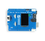
This Github provides getting started guide for Serial Servo based on ESP32.
- Serial Servo powered by ESP32 S3
- In build WiFi/BLE capabilities makes it perfect choice for IoT based projects
- TFT 1.14” display for user interactions
- Two slot to connect Serial Servo Motors, and easily cascade servo to connect more number of motor*
- Three Programmable Buttons to add additional control features to your project
- Type C interface with Reset and Boot buttons available for programming purpose
- Standard 2.54” Header and DC jack options to connect 6-8.4V adapter with onboard regulator
- Power status LED to indicate board power
- GPIOs breakout for additional peripheral interfacing
- Compact and space-saving design
- Compatible Servo Motors =>
*NOTE: Avoid Connecting More Than 6 Servos At A Time, Not Recommended Due To High Current Demand By Servos.
For more details about Serial Servo Motor checkout Manual.
- Microcontroller: ESP32-S3 series of SoCs having Xtensa® dual-core 32-bit LX7 microprocessor
- Connectivity: 2.4 GHz Wi-Fi (802.11 b/g/n) and Bluetooth® 5 (LE)
- Memory: Flash up to 16 MB, PSRAM up to 8 MB
- Board Supply Voltage: 5V
- Operating Pin Voltage: 3.3V
- Operating Servo voltage: 6~8.4V
- Display Size: 1.14”
- Display Resolution : 240x320 pixels
- Display Driver: ST7789
- Display Appearance: RGB, 65K/262K
- Temperature Range: -20°C ~ +70°C

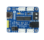
- (1) Serial Servo connector
- (2) Header 2.5” input (6~8.4V DC)
- (3) DC Jack Input (6~8.4V DC)
- (4),(5), (6) Programmable Buttons
- (7) Boot Button
- (8) Type C for Programming/Power
- (9) Reset Button
- (10) TFT 1.14” Display
- (11) ESP32 S3 microcontroller module
- (12) Power Status LED
- (13) & (14) GPIOs and Power breakout
-
Serial Servo Bus Pins:
-
Servo connector having +ve[6~8.4VDC], -ve[GND] and Signal pin.
-
Serial Servo Signal pins breakout into UART RXD and TXD to connect with ESP32 UART pins,
ESP32 Servo Description TXD0/GPIO43 Servo Bus RXD UART communication pin RXD0/GPIO44 Servo Bus TXD UART communication pin
-
-
Display interfacing with ESP32
ESP32 Display Function IO12 LCD_CLK Clock pin of SPI interface for Display IO11 LCD_DIN MOSI (Master OUT Slave IN) pin of SPI interface IO10 LCD_CS Chip Select pin of SPI interface IO13 LCD_DC Data/Command (MISO) pin of SPI interface IO14 LCD_RST Display Reset pin IO9 BL Backlight of display -
Buttons Interfacing
ESP32 Hardware Function IO0 BOOT Boot button IO4 BT1 Programmable Button IO5 BT2 Programmable Button IO6 BT3 Programmable Button -
GPIOs Breakout
ESP32 Type* Multi-Function (Bold-Italic default Function) DM I/O/T RTC_GPIO20, GPIO20, U1CTS, ADC2_CH9, CLK_OUT1, USB_D+ DP I/O/T RTC_GPIO19, GPIO19, U1RTS, ADC2_CH8, CLK_OUT2, USB_D- GND P Supply Ground 5V P Positive Supply, 5V 3V3 P Positive Supply, 3.3V GP8 I/O/T RTC_GPIO8, GPIO8 , TOUCH8, ADC1_CH7, SUBSPICS1 ESP32 Type* Multi-Function (Bold-Italic default Function) GP1 I/O/T RTC_GPIO1, GPIO1, TOUCH1, ADC1_CH0 GP2 I/O/T RTC_GPIO2, GPIO2, TOUCH2, ADC1_CH1 GP42 I/O/T MTMS , GPIO42 GP41 I/O/T MTDI , GPIO41, CLK_OUT1 GP39 I/O/T MTCK , GPIO39, CLK_OUT3, SUBSPICS1 GP38 I/O/T GPIO38 , FSPIWP, SUBSPIWP *I-INPUT, O-OUTPUT, P-POWER & T-HIGH IMPEDENCE
-
Download Arduino IDE from official site and install into your system. We have use Arduino IDE 1.8.19
-
Once installation done will add ESP32 S3 board support into IDE, for this first you need to add below link into preference:
https://raw.githubusercontent.com/espressif/arduino-esp32/gh-pages/package_esp32_index.jsonSelect File > Preference, and add link as show in below image,

-
Now will install ESP32 based boards as shown in below image,

-
Once done, keeping default settings select the ESP32S3 Dev Module with suitable com port (may be different in your case) as shown below,


-
Download library zip file provided here in github.
-
Extract and copy files inside Document > Arduino > Libraries folder. Make sure to restart Arduino IDE whenever you update or add any libraries.


- At this step you are all set to test codes, for easy getting started we have provided various demo example codes in github which you can download and try.
- Open one example code in Arduino and make sure you have selected correct board with suitable com port, click on upload button to transfer code on Serial Servo ESP32.

- Checkout other examples below and build your own custom program codes using those references.

- Schematic
- Hardware Files
- Step File
- Getting Started with ESP32 in Arduino
- ESP32 S3 Hardware Reference
- ESP32 S3 Datasheet
- Arduino IDE 1 overview

This is open source product. Kindly check LICENSE.md file for more information.
Please contact support@sb-components.co.uk for technical support.