LICENCE: CC BY-SA-NC
This is a hobby project and comes with no official support. The PCB schematic and board design files are offered 'as is' with no claims made about their fitness for any specific purpose. As with any device capable of modifying the contents of flash chips and other connectable/communicatable devices, you can affect the operation of the host device, or 'brick' it, if you make a mistake so, just like any other FT232H-based board, you use this one at your own risk.
The FT232H is a versatile multifunction USB to JTAG / UART / FIFO / SPI / I2C chip from FTDI (https://www.ftdichip.com/Products/ICs/FT232H.htm) that has been used on a number of generic interface, flash reader/programmer and signal probing boards - for example:
| Name | Supplier | Ref |
|---|---|---|
| FT232H breakout board | Adafruit | https://learn.adafruit.com/adafruit-ft232h-breakout/overview |
| The Shikra | Xipiter | https://int3.cc/products/the-shikra |
| FT2232H USB 2.0 Hi-Speed breakout board | Seeed Studios | https://www.seeedstudio.com/FT2232H-USB-2-0-Hi-Speed-breakout-board-p-737.html |
| FTDI UM232H-B breakout board | FTDI | https://www.ftdichip.com/Support/Documents/DataSheets/Modules/DS_UM232H-B.pdf |
| FT232H breakout board | CJMCU | Various suppliers |
This project is a baseboard for the CJMCU FT232H module, which is widely available on auction sites for under $8/£6.
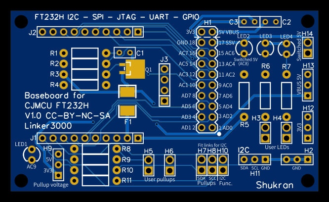
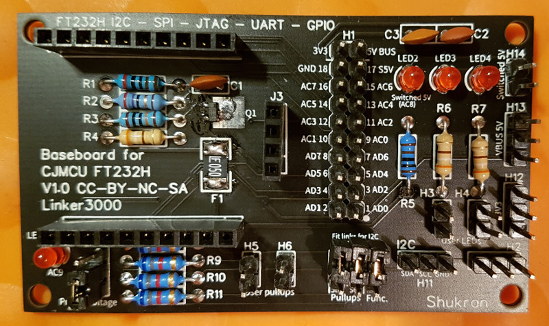
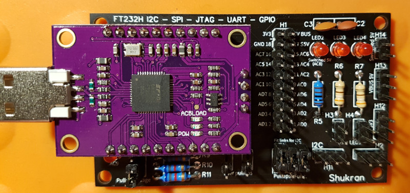
Plugging a CJMCU board onto the Shukran creates an easy-to-use multi-function bus / device hacking and analysis tool with protected (current limited) 5V power pins, 3.3V power, spare pullup resistors and indicator LEDs, all for around $16/£12 total. The Shukran is designed to be assembled by anyone with moderate soldering skills; all components are through-hole except for two larger, surface mount, ones which should be easy to fit with a soldering iron.
(Board V1.01 has slightly modified screen printing but everything else is the same)
A fully-populated Shukran board provides:
- Breakout pins for the FT232H chip ports, and power rails
- A dedicated I2C header
- Two dedicated I2C pullups which can be connected/disconnected as needed
- Two spare pullups which can be connected to the breakout pins and VBUS (5V) or 3.3V as needed
- Two user LEDs which can be connected to the breakout pins as required using dupont jumper leads
- Overload-protected 5V and switched VBUS (5V) connection points
- 3.3V and GND connection points
- A dedicated indicator LED on the AC9 bus line
Unlike some FT232H (and FT2232H) breakout boards, all Shukran 5V power pins are protected by a 500mA polyfuse to reduce the risk of overcurrent conditions or damaging the host USB port.
| Board | Current limited 5V power pins |
|---|---|
| CJMCU FT232H breakout board | NO |
| Shukran + CJMCU FT232H breakout board | YES (polyfuse) |
| Adafruit FT232H breakout board | NO |
| Xipiter The Shikra | YES (polyfuse) |
| Seeed Studios FT2232H USB 2.0 Hi-Speed breakout board | NO |
| FTDI UM232H-B | NO |
The assembled 2-board setup is compatible with many common tools and apps, such as CircuitPython and OpenOCD, with the added bonus that the FT232H part is easily replaced if it gets damaged; just pull off the low-cost CJMCU board and fit a new one - no more writing off an expensive board or having to think about replacing a surface-mount chip!
To make a Shukran, you'll need to order the PCB, required components and a CJMCU board. The PCB design files are at: https://easyeda.com/linker3000/Shukran. Bare boards can be ordered directly from JLCPCB, or you can download the design files and use another manufacturer.
| ID Part | Description |
|---|---|
| C1-C3 | Capacitor 0.1uF 50V ceramic |
| F1 | 500mA polyfuse SMD 1812 eg: Bourns MF-MSMF050-2 |
| J1, J2 | 10-pin 0.1” (2.54mm) header female |
| J3 | 4-pin 0.1” (2.54mm) header female |
| H1 | 2 x 20-pin 0.1” (2.54mm) header male |
| H3, H4, H5, H6, H7, H8, H10, H14 | 2-pin 0.1” (2.54mm) header male |
| H2, H9, H11, H12, H13 | 3-pin 0.1” (2.54mm) header male |
| Q1 | P-channel MOSFET 20V 3.7A SOT23 package eg: IRLML6402 |
| R1 | Resistor 2K 1/4W |
| R2 | Resistor 27R 1/4W |
| R3 | Resistor 100K 1/4W |
| R4, R6, R7 | Resistor 330R 1/4W |
| R5 | Resistor 680R 1/4W |
| R8-R11 | Resistor 6K8 1/4W (or choose your pullup value, say 4K7 or 10K) |
| LED1-4 | 3mm red or green |
| Misc | 4 x PCB jumper links |
| Misc | Dupont hookup/patch wires - as needed |
| Misc | USB 2.0 extension Cable: A Male Plug to A Female to connect the assembled unit to the host computer. |
Using a short USB extension cable is recommended to reduce the physical stress of supporting the two-PCB assembly on the host computer's USB port.
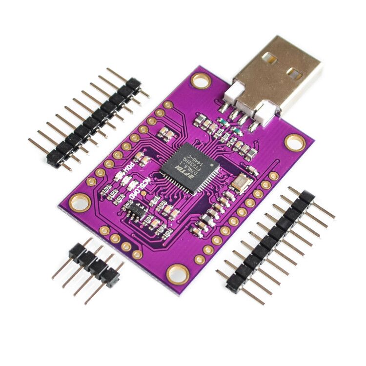
Make sure you buy the right FT232H CJMCU board - check the image below.
The header pins must be soldered to the PCB so they point downwards - this also means it's important to buy boards that don't have the header pins pre-soldered to the top of the PCB.
The board has a power LED and two LEDs fitted to FT232H pins AC3 and AC4. In UART mode, AC3 and AC4 are intended to be used to drive RxLED and TxLED indicators, but they have to be defined as such otherwise they will do nothing unless you specificially control them - see the FTDI docs for the chip and the section below on RxTx LEDs.
The Shukran has a main header (H1) which breaks out the FT232H pins and also provides access to power as follows. All I/O pins are 3V3, 5V tolerant:
| Shukran H1 header pin | FT232H pin |
|---|---|
| 1 | AD0 |
| 2 | AD1 |
| 3 | AD2 |
| 4 | AD3 |
| 5 | AD4 |
| 6 | AD5 |
| 7 | AD6 |
| 8 | AD7 |
| 9 | AC0 |
| 10 | AC1 |
| 11 | AC2 |
| 12 | AC3 (often used as RxLED in Async mode - see above notes about the CJMCU board) |
| 13 | AC4 (often used as TxLED in Async mode - see above notes about the CJMCU board) |
| 14 | AC5 |
| 15 | AC6 |
| 16 | AC7 |
| 17 | 5V, switched on/off by AC8, NB: This signal is not controllable via regular I/O programming. See FTDI docs. |
| 18 | GND |
| 19 | 5V (VBUS) |
| 20 | 3V3 |
In keeping with other designs, AC9 is connected directly to an indicator LED and is not available on a header pin.
Follow the online FT232H examples to connect the correct pins from the Shukran to the target circuit. The pinouts given below are typical but some programs may use different ones.
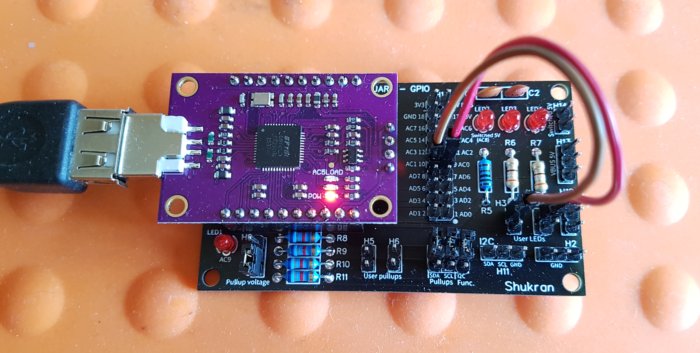
The user LEDs are for monitoring the state of I/O pins. Connect a jumper wire from the top header pin on H3 or H4 below an LED to the required I/O pin and the second H3/H4 header pin is now also connected to the I/O pin. The LEDs are connected via a resistor to VBUS (5V) and so they will light up when the I/O line is pulled to ground because the FT232H ports are open drain.
In the above picture, the user LEDs are jumpered to show the state of AC0 and AC1. To make other connections to those lines, the second pins on H3 and H4 are used.
The CJMCU board has LEDs attached to FT232H lines AC3 and AC4, and the Shukran board has an LED permanently connected to AC9 in accordance with the FT232H reference design. These LEDs can be used as Rx/Tx indicators for async comms, however to set them up as such requires the FT232H's initialisation config to be modified.
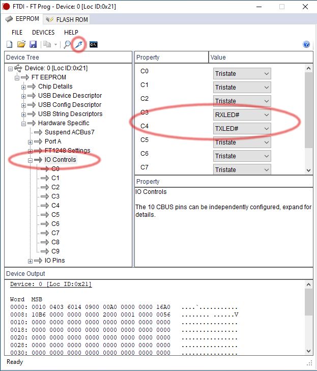
The FT232H architecture supports an EEPROM for storing chip configuration information (there's one on the CJMCU board), and FTDI provides a Windows-based tool called FT_PROG for setting-up this info - see: https://www.ftdichip.com/Support/Documents/AppNotes/AN_124_User_Guide_For_FT_PROG.pdf
Observe the cautions about this utility - applying some settings may stop the FT232H from functioning.
There is also a linux-based flash read/write tool called ftdi_eeprom that comes with the libftdi driver bundle - BUT at the time of writing it does not work properly with the FT232H chip!
The folks at Xipiter wrote a tool in Python to set various options on their 'Shikra' (FT232H) board, and because it's also based on the FTDI chip reference design, this tool also works with the Shukran. You will find the tool here: https://github.com/Xipiter/shikra-programmer. There's also a modified version here: https://github.com/linker3000/shikra-programmer.
The modified version fixes an issue with the original that requires the default FTDI chip kernel module to be removed with rmmod in order for the tool to claim access to the board.
This tool allows AC9 to be defined as the async RxTx LED (read the instructions on the Github page), however it does not support setting AC3/4. Fortunately, the tool does allow FT232H flash memory backups to be taken and restored, and this repo includes three hex files that can be used to set and unset the Rx Tx LEDs by restoring the relevant file:
| File | Description |
|---|---|
| default.hex | Sets board back to defaults (no LEDs in use) |
| c9rxtx.hex | AC9 LED set as async RxTx indicator |
| c3rxc4tx.hex | AC3 = Rx, AC4 = Tx |
Once the required file has been restored, the board needs to be unplugged/replugged to reinitialise the FT232H with its new settings.
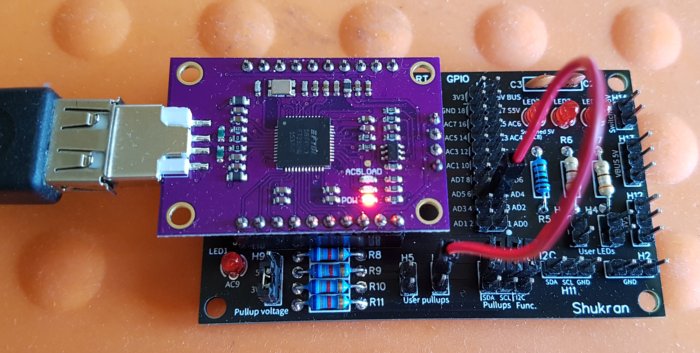
There are two unassigned pullup resistors for use as needed; connect a jumper wire from either pin of H5 or H6 to the required I/O line and the second pin on the header is now also connected to the I/O pin.
In the above picture, there is a pullup connected to AD4. To make a connection to that line, the second pin on H6 is used.
Fitting jumpers on H7 and H8 (marked SDA and SCL for I2C use), connects pullups to AD1 (SDA) and AD0 (SCL) respectively. These pullups can be used as needed, even for non-I2C protocols.
NB: The jumper position on H9 determines whether the pullup resistors are connected to 5V (jumper on top two pins) or 3.3V (bottom two pins).
By default the FT232H chip starts in Async/Serial mode - so when you plug in a CJMCU/Shukran board, you should see a new COM or /dev/ttyUSB port appear on your system and you can just go ahead and use it with a serial program such as TeraTerm or Minicom etc.
| Function | FT232H pin | Shukran H1 pin | Direction |
|---|---|---|---|
| Tx | AD0 | 1 | OUT |
| Rx | AD1 | 2 | IN |
| RTS* | AD2 | 3 | OUT |
| CTS* | AD3 | 4 | IN |
| DTR* | AD4 | 5 | OUT |
| DSR* | AD5 | 6 | IN |
| DCD* | AD6 | 7 | IN |
| RI* | AD7 | 8 | IN |
| RxLED** | AC3 + LED on CJMCU board | 12 | |
| TxLED** | AC4 + LED on CJMCU board | 13 | |
| GND | GND | GND |
*These optional signals may not be driven/read by some example programs.
**See previous section on RxTx LEDs
To operate the board in any other mode requires software to setup and control it; for example, CircuitPython or OpenOCD etc. For more info, see the reference material at the bottom of this readme and the python examples in this repository.
In I2C mode, the following pins/connections should be used:
| Function | FT232H pin | Shukran H1 pin | Pullup (if needed) |
|---|---|---|---|
| SDA | AD1 + AD2 | 2 + 3 (linked) | Jumper on H7 |
| SCL | AD0 | 1 | Jumper on H8 |
| GND | GND | GND |
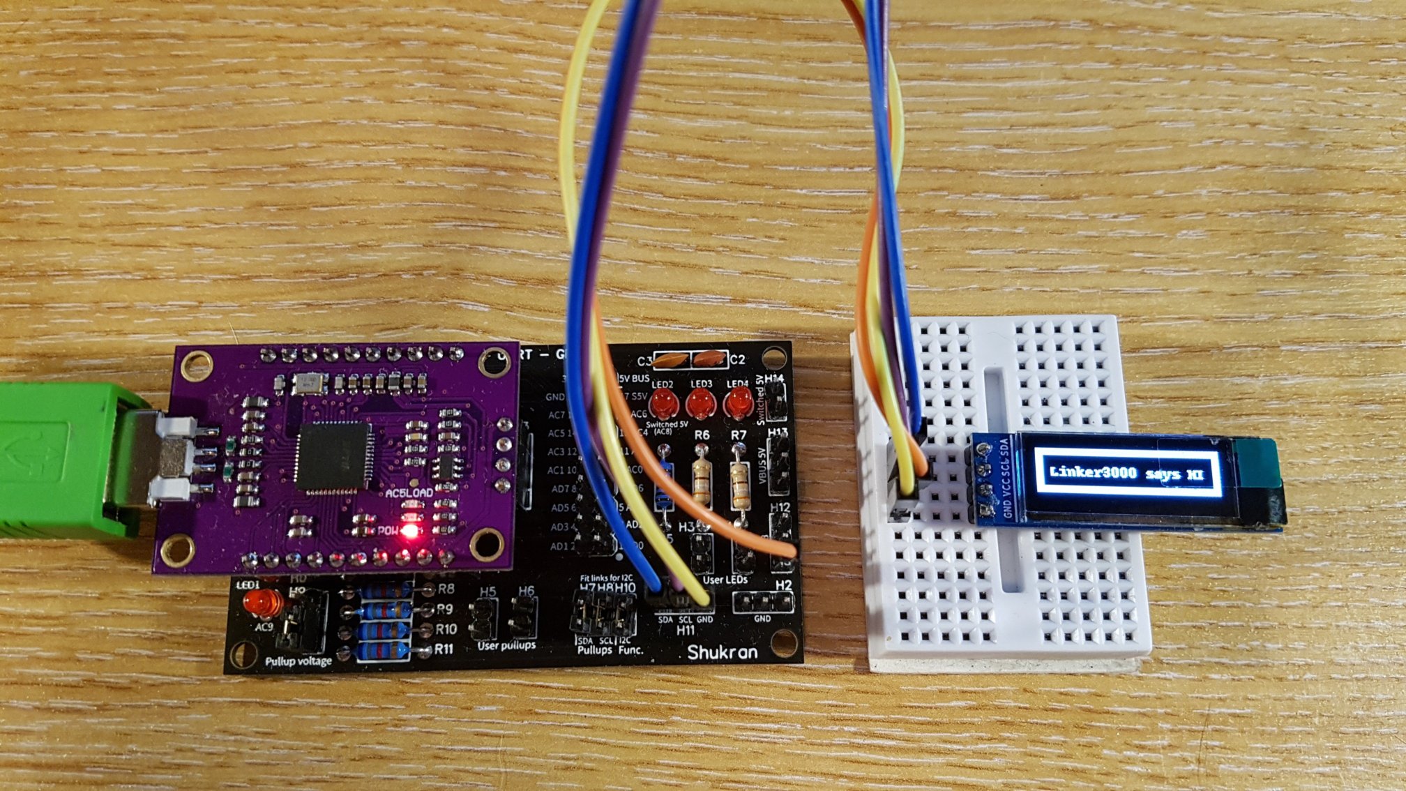
To make hookups easier, the board has a dedicated I2C header, designated H11. To use this header:
- Fit a jumper on H10 - this links FT232H pins AD1 and AD2 together.
- Fit H7 and H8 jumpers if needed to hook up the SDA and SCL pullup resistors. NB: The FT232H has no internal pullups.
NB: The jumper position H9 determines whether the pullup resistors are connected to 5V (jumper on top two pins) or 3.3V (bottom two pins).
You can now connect your I2C patch leads to SDA, SCL and ground on H11.
REMEMBER TO REMOVE ANY JUMPERS ON H7 H8 and H10 WHEN NOT USING I2C MODE.
| Function | FT232H pin | Shukran H1 pin |
|---|---|---|
| SCK | AD0 | 1 |
| MOSI (SDI) | AD1 | 2 |
| MISO (SDO) | AD2 | 3 |
| CS | AD3 | 4 |
| GND | GND | GND |
| Function | FT232H pin | Shukran H1 pin |
|---|---|---|
| TCK | AD0 | 1 |
| TDI | AD1 | 2 |
| TDO | AD2 | 3 |
| TMS | AD3 | 4 |
| GND | GND | GND |
Use H1-1 to H1-8 (AD0-AD7) and H1-9 to H1-16 (AC0-AC7) as per the setup of your program.
Inspiration and how-to-use guidance can be found at the following places:
https://www.ftdichip.com/Products/ICs/FT232H.htm
https://learn.adafruit.com/adafruit-ft232h-breakout?view=all
https://learn.adafruit.com/circuitpython-on-any-computer-with-ft232h
https://eblot.github.io/pyftdi/index.html
https://github.com/unprovable/FTDI-Oh-My
https://github.com/kkrizka/adafruitft232h_i2c_adapter
https://github.com/linker3000/shikra-programmer
http://dangerousprototypes.com/docs/FT2232_breakout_board
https://int3.cc/products/the-shikra
http://www.openocd.org/doc/html/Debug-Adapter-Hardware.html
https://plaes.org/technotes/embedded-systems/ftdi-ft232h-for-hardware-hacking
(Use 270R-470R resistor for 'R' in the diagram)
