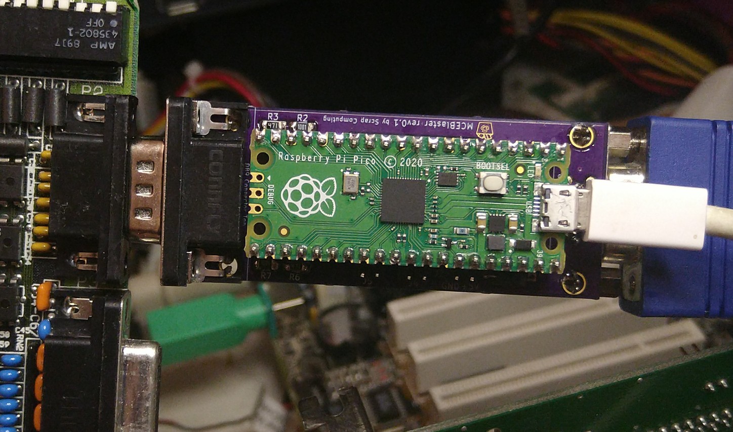
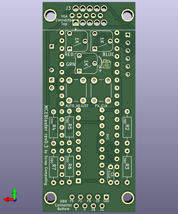
A simple standalone MCA/CGA/EGA to VGA adapter based on a raspberry pi Pico.
- MCE Blaster video part 2: https://www.youtube.com/watch?v=Neg1WR7Hz5s
- MCE Blaster video part 1: https://www.youtube.com/watch?v=kgDOiGoxKvE
The Pico reads the TTL input video signal, writes the pixels to a buffer and then generates the VGA signal using the pixels from the buffer.
- No need for a VGA upscaler or a 15KHz VGA monitor. Works with standard VGA modes.
- Pixel-perfect output:
- VGA 640x400 for CGA/EGA 320x200,640x200 and 640x350 inputs
- VGA 800x600 for MDA 720x350
- Pixel clock tuning for each mode
- Auto-adjustment functionality that centers the image on screen
- EGA brown color correction
- On-screen messages
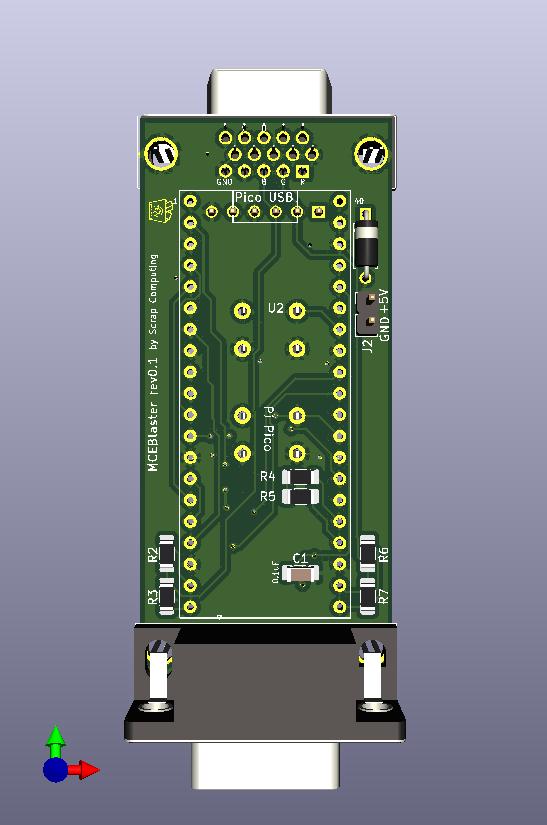
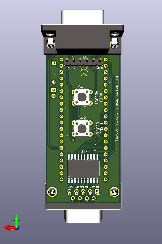
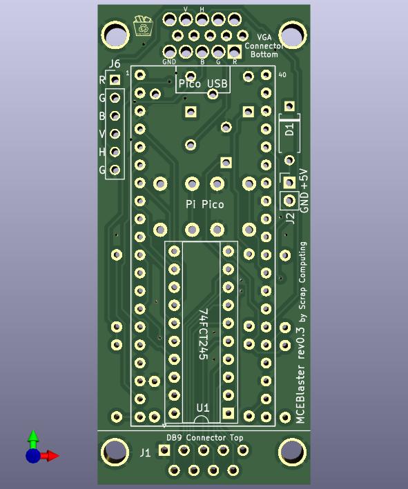
- Two PCB variants, one SMD and one Through-Hole.
- Download firmware (MCEBlaster.uf2): https://github.com/scrapcomputing/MCEBlaster/releases
- Unplug the Pico
- Press and hold the small "BOOTSEL" button on the Pico
- While holding the BOOTSEL button, connect the Pico to your PC with a micro-USB cable
- The Pico should show up as a mass-storage device
- Copy the
MCEBlaster.uf2firmware to the drive associated with the Pico - Safely eject the mass-storage device
- Push the
PIXEL CLOCKbutton once, this will enter the pixel adjust mode. - Pushing
PIXEL CLOCKagain will increment the pixel clock by 10KHz. - Medium-pushing (about 1 second push)
PIXEL CLOCKwill increment by 1KHz - Pushing
AUTO ADJUSTwill decrement by 10KHz. - Medium-pushing (about 1 second push)
AUTO ADJUSTwill decrement by 1KHz. - Exit pixel clock adjust mode by not pushing any buttons for a few seconds. This won't save the settings to flash.
- Save settings to flash memory by long-push (keep pushed until you see message)
PIXEL CLOCK.
- Push the
AUTO ADJUSTbutton. This works best when the image shown is full from border to border. - Long-push the
AUTO ADJUSTbutton turns on continuous auto-centering mode. This may be useful occasionally, but won't work well if the image is mostly blank as it may keep re-adjusting the image.
The first core reads the TTL video data (through the level-shifter) from a PIO state-machine and places the pixels onto a buffer in memory. The second core works completely independently from the first core and reads the pixel from the buffer and feeds them, along with the necessary Horizontal and Vertical Sync signals to a PIO state machine that writes to GPIO outputs. The output is converted to analogue with the help of a simple R-2R DAC consisting of two resistors. Feel free to check out the video part 1 for a visual overview.
The PIO state machines are used not only receiving the TTL video data and writing the VGA video data, but also for other helper functions including:
- Detecting no input signal: This checks if the horizontal sync signal is active.
- Detecting the image offset: This counts the black border pixel until a non-black pixel is found across all lines. This count is used for centering the image automatically.
- The EGA PIO state machine also does the Brown pixel fix because the overhead of doing that in a CPU core was too high.
The TTL video input is read by a PIO state-machine (one version for each video mode). But getting it to sample the pixels at the right time requires us adjust the sampling period in a precise way to match the TTL video card's internal pixel clock. Using the PIO clock divider does not give us a good-enough precision, because the fractional part of the divider is an 8-bit number, meaning that we get precision of ~0.004ns, but what we really need is about 0.001ns. So what we do is that we have multiple implementations of the state-machine code, each with a different sampling period and we look for the one that has the lowest division error using the PIO's 8-bit divider. This process is explained in more detail in the video part 2.
There are two versions of the PCB available:
- The SMD version, and
- The Through-hole version (with the
_THTfile suffix)
So please select the parts according to the PCB version you are planning to build.
Download gerbers: https://github.com/scrapcomputing/MCEBlaster/releases
| Reference | Quantity | Value | Description |
|---|---|---|---|
| C1 | 1 | Capacitor SMD 0.1uF 1206 (or disk ceramic for Through-Hole) | Decoupling capacitor for level-shifter IC |
| D1 | 1 (optional) | Diode Through-hole (e.g., Schottky 1N5817 or silicon 1N4001) | For powering the MCE Blaster from the PC (instead of the Pico's micro-USB) |
| J2 | 1 (optional) | 1x02 through-hole Male PinHeader 2.54mm | For alternative external power |
| J1 | 1 | DB9 Male Horizontal | For connecting to TTL video card |
| J3 | 1 | DB15 Female HighDensity Connector | For connectint to VGA monitor |
| R3 R4 R6 | 3 | 422 Ohm 1206 SMD (or Through-hole) resistor 1% (alternatively 470 Ohm) | For VGA signal DAC |
| R2 R5 R7 | 3 | 845 Ohm 1206 SMD (or Through-hole) resistor 1% (alternatively 1K Ohm) | For VGA signal DAC |
| SW1,SW2 | 1 | 6mm Through-hole push button | Auto-adjust and pixel-clock buttons |
| U1 | 1 | 74LVC245 SO-20 SMD 12.8x7.5mm aka SOIC (or DIP-20 + optional socket for Through-hole) | Level-shifter IC |
| U2 | 1 | RaspberryPi Pico | Pi Pico |
| N/A (for Pico) | 2 | 1x20 female through-hole pin-header 2.54mm pitch | PCB Pico headers |
| N/A (for Pico) | 2 | 1x20 male through-hole pin-header 2.54mm pitch | Headers for the Pico |
- https://minuszerodegrees.net/mda_cga_ega/mda_cga_ega.htm
- https://en.wikipedia.org/wiki/IBM_Monochrome_Display_Adapter
- https://en.wikipedia.org/wiki/Enhanced_Graphics_Adapter
- https://en.wikipedia.org/wiki/Color_Graphics_Adapter
- https://en.wikipedia.org/wiki/VGA_connector
- Rev 0.1: Initial release.
The project is GPLv2.
