This project aims to bring the Linuxcnc HostMot2 code from Mesa Electronics to more boards. For maximum portability it is based on Litex a framework to easily build SoC on FPGA boards.
The first board we bring hostmot2 to is the linsn rv901t, a low cost board originally designed to control LEDs, but which is well suited to serve as a general I/O board. Information about the reverse engineered board can be found here.
There are a few hurdles to take to get up and running.
- Do the initial firmware programming
- Modify the board for input and output
- Build a breakout board
- Rebuild LinxCNC hostmot2 driver
If none of the provided configurations fit your needs, you can either open a ticket to get your configuration included or build it yourself.
To get started you need to flash or load the first bitstream via external means. After that, you can use mesaflash or the serial interface to do updates. For the initial programming you can choose any of the provided bitstreams.
You can either program the flash directly via header JP5 or via JTAG. A running litehm2 identifies itself by emitting short flashes with the onboard LED (green).
Example bitstreams can be found in bitstreams, where the .bin
files are for direct flash programming and the .bit files to load via JTAG.
To program the flash directly you need to find an adapter that is supported by flashrom. A cheap option is an ftdi ft2232h or ft232h based board.
As the SPI header (JP5) has only 2mm spacing, common connectors do not fit. An easy option is to use Dupont-style jumper cables and remove every other one from its housing (example).
Make sure to connect PROG_B to GND. This instructs the FPGA to release its SPI interface. You probably also have to reduce the clock rate when using ftdi(2)232h-based modules using the 'divisor' option (see manpage of flashrom).
The current version of flashrom does not recognize the onboard SPI flash. Nevertheless programming works.
For initial programming bitstreams/initial.bin should be used. This is a padded version of litehm2.bin, as flashrom expects the file to be the same size as the flash to be programmed.
The other option is to do the JTAG hack as described here and use openFPGAloader.
openFPGAloader can also be used to program the flash with --write-flash (untested). Otherwise you can use mesaflash to do the programming once the bitstream is loaded.
After initial programming mesaflash can be used to write a fallback bitstream to the board. First, the fallback-boot header needs to be written:
mesaflash --addr 10.10.10.10 --device ether --write bitstreams/litehm2.bit --fix-boot-block
Then the fallback stream can be programmed.
mesaflash --addr 10.10.10.10 --device ether --write bitstreams/litehm2.bit --fallback
Regular updates can be done with
mesaflash --addr 10.10.10.10 --device ether --write bitstreams/litehm2.bit
The rv901t has 11 bidirectional drivers with 8 ports each, of which 3 are hardwired to output. The other 8 can be switched to input or output, but only all at once. So you basically have two options here:
- Use 2 boards, one for output, one for input,
- Modify a board to get a mixture of both.
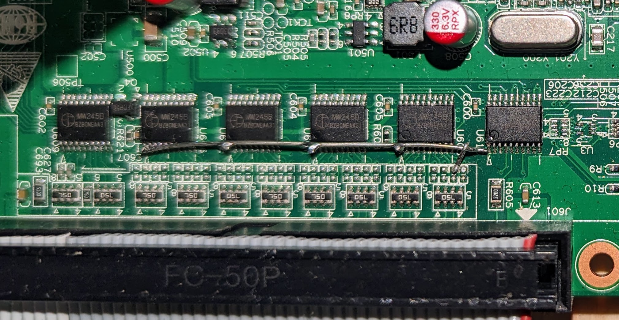
I have modified my board so that the upper row is always configured as output, while the bottom row is switched to input via software. The modification is quite simple. Lift up the direction pins of U603, U607, U602 and U606 (see rv901 front annotated) and connect them to ground. You can find ground on any of the unpopulated resistors, on the side closer to the drivers.
Two easier ways to modify the board are described in this post by Ilya Koubatkin.
Because the board already has 5V-compatible inputs and outputs, it is very easy to build a simple breakout board. The drivers also already add some level of protection.
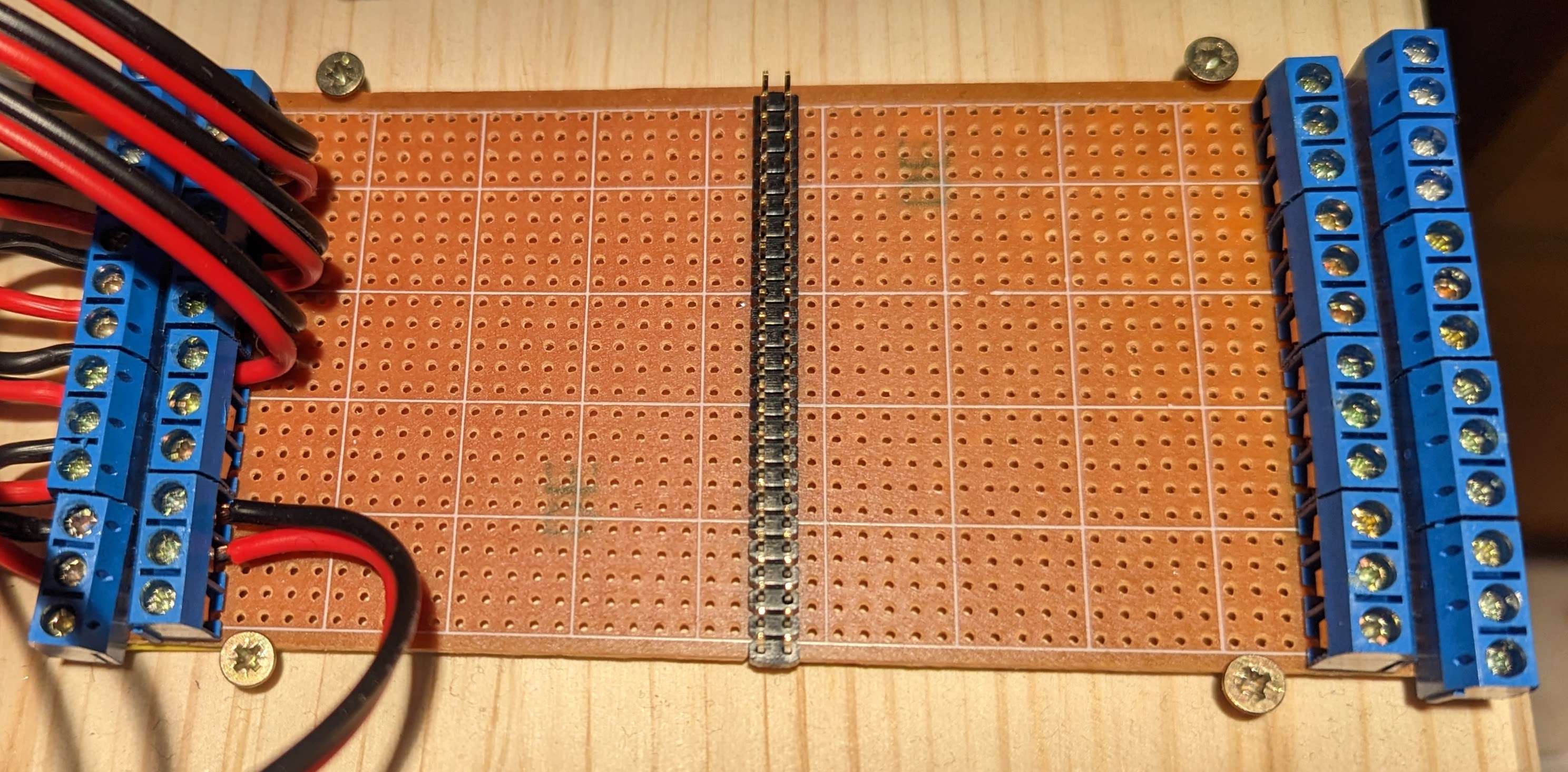
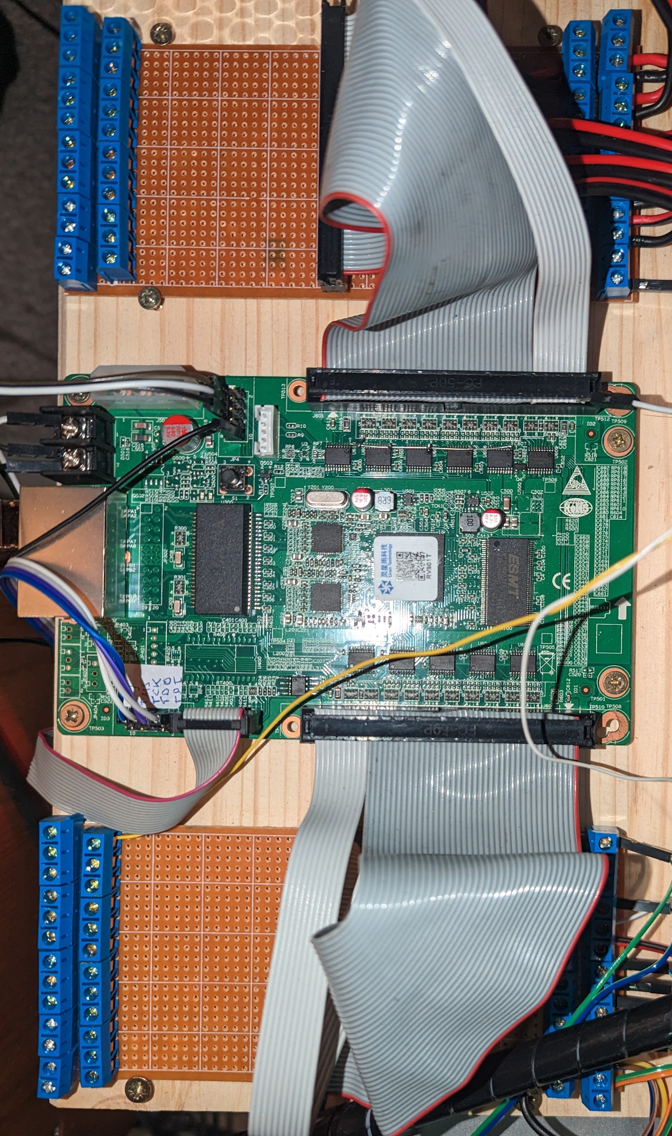
I just mounted a 50 pin header to a vero board, cut the strips between the pins and added 5.08mm pitch screw terminals. This way I get 4 rows of screw terminals, the outer ones with 13 terminals and the inner ones with 12. The board is connected to the breakout board with a short ribbon cable with IDC connectors. Pin one is connected pointing down on each board.
With two breakout boards, one on top of the board and one on bottom, I have a total of 8 columns of screw terminals. In the configuration file I named them top-left-outer (tlo), top-left-inner (tli) ... bottom-right-outer (bro). Pin 1 is always to the bottom.
The I/O configuration of the board is defined by board.conf. The provided config is what I use for my machine, with 3 axes and gpio for input and output.
The file itself should be fairly self-explanatory. First it defines aliases
to map the board header names (J600/J601) to the names of on the breakout
board. Then the pins are assigned functions. a ! in front of the function name
means to negate the output. This is used to easily configure differential
outputs.
Currently hm2_eth sends a burst of messages on startup which overwhelm the rv901t due to its gbit interface. To mitigate this, pull commit 2afcf903 from sensille/linuxcnc-litehm2 or build linuxcnc from master. The patch is merged and will probably be part of the 2.10 release.
Then rebuild linuxcnc according to building linuxcnc.
The list of known boards in mesaflash needs to be extended by the litehm2 definition. After that it can be used to flash the firmware, including fallback boot. It can also set the IP address. Config-reload is currently not yet supported, after flashing a new firmware a power cycle is necessary.
Build mesaflash from sensille/mesaflash-litehm2.
A pull request has also been submitted.
As a starting point I added the configuration of my 6040 (example, upgraded to closed loop stepper drivers, vfd control via modbus (via a separate USB dongle) and 3 probe inputs (tool length sensor, 3d probe and electrical contact).
I generated this config with pncconf and heavily modified it from there. A future goal would be to be able to generate a usable config directly from pncconf and mesact.
To build the project, you need the following prerequisites:
- Litex (default setup)
- Risc-v toolchain
- Xilinx ISE 14.7
At the time of this writing a small patch to litex-boards is needed, you can find it here. Also make sure to get the master version of litex (core), as it contains a fix needed.
To build, just type make. ./litehm2.py only builds the SoC and generates
the verilog files. The Makefile also contains a workaround for
#1502.
The resulting bitstream is copied to the bitstreams folder.
Inside board.conf you can basically use all available hostmot2 modules, although currently only stepgen, pwm and gpio are implemented. To add more modules, just add the corresponding config lines to hostmot2.py or open an issue.
Should you get during build an error like
ERROR: Could not detect Ninja v1.8.2 or newer
the problem can be that the Xilinx installation interferes with the sytem
libraries. A workaround is to run make without the Xilinx paths in
LD_LIBRARY_PATH. So call LD_LIBRARY_PATH= make for the first run,
so meson can build the required files. After that running with the xilinx env
should work.
Litehm2 takes the original hostmot2-entity and integrates it into a SoC. The mesa-d16w CPU is replaced by a RISC-V cpu, vexriscv and the assembler code rewritten in C. This mainly implements the LPB16 protocol and rudimentary IP/UDP/ICMP/ARP.
The SoC contains three memory areas.
- ROM: This contains the full firmware plus a serial loader code
- RAM: This area is normally left empty and is only used to hold a dynamically loaded version of the firmware. Used for rapid development cycles.
- SRAM: RAM to be used by the firmware, be it from ROM or RAM.
The RAM area could be ommitted in a future release version.
You can reach me as sensille in #linuxcnc irc-chat on libera.chat.
- add more boards
- use InM and OutM instead of GPIO
- make pncconf and mesact work out of the box
- ...
This project is published under the BSD 2-clause (TBD) license.
The HostMot2 code is Copyright (C) 2012, Peter C. Wallace, Mesa Electronics.


