Template MPLAB X Project for SensiML
Contents
- Overview
- Knowledge Pack Deployment
- Knowledge Pack Integration
- Firmware Operation
- Visualization with SensiML Open Gateway
Overview
This repository contains an MPLAB X project that can be used as a starting point for running any SensiML Knowledge Pack on the PIC-IoT Development Board with the MIKROE 6DOF IMU2 Click Board. Read on for instructions on how to go from a SensiML Knowledge Pack deployment to a full working MPLAB X project.
Hardware Used
Software Used
Related Documentation
Knowledge Pack Deployment
To deploy a knowledge pack for the PIC-IoT Development Kit:
- Open up your SensiML project in the Analytics Studio and navigate to the Download Model tab.
- Select
Microchip PIC-IoT Development Boardfrom the HW Platform options. - Select one of Binary, Library or Source from the Format options. Note: source format is only available for upper tier customers.
- Select the appropriate sensor configuration for your project from the Data Source options. Note that this configuration should match the one you used to capture the data your model was trained with.
- Click the Download button to download the model.
Knowledge Pack Integration
Library Format
If you deployed a knowledge pack in the Library format, the archive should contain a complete, ready to compile, MPLAB X project. Follow the steps below to compile your project:
- In MPLAB X, open up the .X project folder under the
firmwarefolder of the knowledge pack - Ensure that the new knowledge pack has replaced the one supplied in this archive.
Your project should now be ready to compile.
Source Format
If you deployed a knowledge pack in the Source format there are a few manual steps to add the required sensiml files to the MPLAB X project:
- In MPLAB X, open up the .X project folder under the
firmwarefolder of this repository. - In the Projects pane, right click the Header Files folder under the template project and select Add Existing Items from Folders from the options.
- In the resulting window that opens, click the Add Folder button.
- In the new dialog, select Header Files from the Files of Type dropdown, then navigate to the template project's
firmwaredirectory and select theknowledgepackdirectory. Click the Select button to add the directory. - Back in the Add Files window, click the Add button to finish adding the necessary header files and close the dialog.
- Right click the Source Files folder in the Projects pane and select Add Existing Items from Folders from the menu. Repeat steps 4-6 to add all source files (.c files) from the
knowledgepackfolder.
Your Knowledge Pack is now integrated into your MPLAB X project. You should be able to compile your project and flash it onto the PIC-IoT Development Board.
Firmware Operation
The firmware behavior can be summarized as operating in one of three distinct states as reflected by the onboard LEDs and described in the table below:
| State | LED Behavior | Description |
|---|---|---|
| Error | Red (ERROR) LED lit | Fatal error. (Do you have the correct sensor plugged in?). |
| Buffer Overflow | Yellow (DATA) and Red (ERROR) LED lit for 5 seconds | Processing is not able to keep up with real-time; data buffer has been reset. |
| Running | Yellow (DATA) LED flashing slowly | Firmware is running normally. |
When operating normally, the firmware prints the classification prediction (classification ID number) and the generated feature vector for each sample window over the UART port. To read the UART port use a terminal emulator of your choice (e.g., MPLAB Data Visualizer's integrated terminal tool) with the following settings:
- Baudrate 115200
- Data bits 8
- Stop bits 1
- Parity None
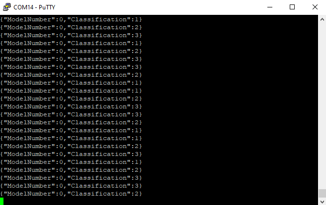
A sample of the terminal output is shown in the figure below. Note the knowledge pack used for this example produces a test pattern 1,2,3,3,2,1...
 |
|---|
| UART Terminal Output |
Note that by default the feature vector will not be output. You can enable this behavior by setting write_features=1 in sml_output.c.
Visualization with SensiML Open Gateway
In addition to reading the text output of the firmware with a terminal emulator, the output may be visualized with the SensiML Open Gateway application. Follow the below instructions to get started:
- Open a terminal and change to the directory where you've checked out this repository.
- Clone the open-gateway repository and install the dependencies:
git clone https://github.com/sensiml/open-gateway
pip install -r open-gateway/requirements.txt - Change the baudrate (
BAUD_RATEvariable) inopen-gateway/config.pyto 115200 - Change to the open-gateway directory and run the open-gateway application, passing in the knowledge pack model.json description file:
cd open-gateway
python app.py -m $(find ../firmware/knowledgepack/ -name model.json) - Connect to the PIC-IoT Development Kit in the gateway application:
- Select the
Recognitiondevice mode. - Select
Serialconnection type, and enter the UART address (e.g. COM4) in theDevice IDfield. - Click
Connect To Device.
- Select the
- Switch to the
Test Modetab and clickStart Stream.
