A fork of https://github.com/maraid/Jarvis, with a DOIT esp32 DevKit v1 and some not-so-beautiful wiring.
- Initially I forked https://github.com/tjhorner/jarvis-desk to https://github.com/shadow1runner/jarvis-desk; I wired everything as stipulated there, but was not really successful (most likely I had some wires wrong or did some wrong code modifications); anyway, doing more research let to...
- ... the current iteration which, in comparison to the former, uses one logic shifter less, since only the UART connectivity is required
- I had a
DOIT esp32 DevKit v1at hand, which also features anESP32-WROOM-32(just as upstream does), but:- it has voltage regulators from 5V to 3.3 V already built-in
- can be powered from 5V (provided by the desk) via its
VINpin [1]
- thus, there was no need of having
- the
CP2102NUSB/UART adapter - the USB-C receptacle
- 3V3 voltage regulator
- the
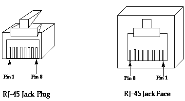
- changed the GPIO pins based on the PinOut shown below

| RJ45 Pin [^0] | Color LAN cable | Schematic Name | New DOIT esp32 DevKit v1 GPIO Pin | New wire color | Note |
|---|---|---|---|---|---|
| 1 | orange/white | DESK_1 |
GPIO32 |
purple | |
| 2 | orange | DESK_2 |
GPIO16 (RX2) |
white | UART |
| 3 | green/white | GND | N/A (GND) | ||
| 4 | blue | DESK_4 |
GPIO17 (TX2) |
gray | UART |
| 5 | blue/white | +5V | N/A (+5V) | ||
| 6 | green | DESK_6 |
GPIO33 |
blue | |
| 7 | brown/white | DESK_7 |
GPIO25 |
||
| 8 | brown | DESK_8 |
GPIO26 |
[^0]
- As usual: DON'T try getting it running on Windows, just get a Linux somewhere (e.g., a Raspberry) and you are good to go via running setup.sh
- useful commands, after
cd firmware:esphome run jarvis_withsecrets.yamlcompiles and flashes the firmware to the board; note that you shortly need to press itsBOOTbutton such that the flashing can happenesphome run debug.yamlin case you need more informationesphome logs debug.yamlfor connecting toLOGGER(UART0)
jarvis-deskis configured to auto-reconnect to known WiFi networks; in case this fails, it goes into AP mode and spawns a network namedFully Jarvis Fallback Hotspot- connect to said WiFi, using the initial password
Einstieg00 - once there, it asks you to join a "real" WiFi, simply select one from the list and enter the password
jarvis-deskwill reboot and (try to) connect to known WiFi networks
- after connecting to a known WiFi network (cf. Connect to jarvis-desk the very first time?), you should be able to connect via http://jarvis-desk.local
- otherwise check your home network for the IP address of the device named
jarvis-desk; also make sure that ublock origin is not blocking any externally loaded resources - there you can change settings (like units etc.)
- Rebase and push changes to
origin - now either:
- On gitHub:
- start a new release which will cause the CI pipeline to create a new firmware
- download the release binaries, the
firmware.binis the file you need - navigate to http://jarvis-desk.local via a browser and upload said binaries which will perform an OTA upgrade
- On your local development environment:
- run
esphome run config.yaml, which compiles and flashes the firmware to the board; note that you shortly need to press itsBOOTbutton such that the flashing can happen
- run
- On gitHub:
This project is a ESPHome component for fully's Jarvis standing desk.
It enables Home Assistant to control the desk and get data out of it. It has all the features from the official handset and more. It's a man-in-the-middle device to control all UART messages between the desk's controller and the handset.
Originally I wanted to be able to control the desk from a Home Assistant automation so I started looking if there are any projects that has done this already. Luckily, I came across Phil Hord's IoT project, which I strongly recommend to check out. He has done the reverse engineering of the communication and the wiring that I extensively used to create this project. In the beginning I tried to make that work for Home Assistant but during that I realized that I could probably use the screen for other things (temperature, humidity, stock market changes?).
So I started reverse engineer it even further. I discovered, through fuzzing about 2 dozen of message types that were not used by neither the controller nor the handset in the stock configuration and managed to exploit some bugs as well that I found during the journey. With all that knowledge I decided to implement a man-in-the-middle device that captures all traffic and is able to inject fake messages into both of the data streams.
There were 3 things I wanted to have: (1) The ability to turn the screen on anytime for notification (this I think is impossible). (2) Always-on display to show numbers without activating the screen. I really didn't like touching it twice to move it. (3) Custom numbers on the display to have something more useful than the current height, which is almost completely useless for me.
- All controls that the handset provides
- Capture all and inject fake UART messages
- Always-on LCD display
- Custom number display (0-180)
- ESPHome configuration
Exploit that has been implemented so far:
- Always-on LCD display
Exploits that has not yet been implemented:
- Always-on leds with no display
- Always off leds and display but active handset. "Dark mode"
Check out Phil's repository for details on the wiring and the communication protocol.
Google Sheet containing all the notes I took
Important findings:
- The "handset control lines" are unnecessary. Everything can be done via UART messages.
- Display behavior:
- When 0x01 (height report) is received by the HS (Handset), normally it gets stored in memory (0x1B) and then displayed.
- If 0x01's payload is outside the display's range (1-1800) it won't be written to memory, but the content of 0x1B will be shown. (i.e. the last value sent)
- 0x1B can be set by hand without updating the display. Can be set to 0, so the next out-of-range 0x01 will show 0. It cannot be set above 1800.
- The screen turns off if the received 0x01 is the same as the number in 0x1B for ~9 seconds. This means that if an out-of-range number is being sent periodically (0 or anything above 1800) the screen won't turn off, since 0x1B won't be updated.
- Some errors can turn it on in off mode without touching, but I found no way to keep it active, it always goes to sleep mode after the error disappears.
- I found no way of changing brightness or locking the handset since these are self contained.
- Controlbox:
- Kill mode: disable anti-collision. It's not possible through the handset for some weird reason.
- You can get the current settings with 0x07. Check the sheet for details.
- No motor frequency change or anything too crazy unfortunately.
- I managed to crash it a couple of times, rendering it unresponsive, but I cannot reproduce it. A simple power cycle fixes it though.
- (exploitable) Bugs:
- Empty screen, active buttons: On powerup the hanset turns on and starts spamming 0x29 until answered. Goes to sleep in about 10 seconds after showing "fully" logo. Next time it's pressed it wakes up the controller with signallines. However, if no answer is received then the buttons stay lit and active and the screen is blank.
- Dark mode: Sending 0x23 to the sleeping handset will put it in an errornous state if 1 or 2 send in P0. The lights will not turn on until reboot. Everything else behaves the same way. No way found to reset it without power cycle. (Same applies to error satetes 0x01 - 0x0D and 0x10)
- Home Assistant
- Wemos D1 Mini. Or whatever ESP8266 board you find at home.
- A bit of soldering.
In progress...