You probably want to view 1402-schematics.pdf.
I've redrawn IBM 1402 schematics in KiCad to make them more readable, specifically the relay logic for the reader. The original schematics draws the relay logic in a way that is almost impossible to follow: crammed together and split across pages. (Even so, these schematics probably won't make sense to the modern reader.)
This section discusses a methodology for debugging feed or clutch problems electrically. It is easy to examine the feed signals from the 1402 to check if they are being generated correctly.
The feed and clutch process requires cooperation between the 1402 card reader and the 1401 computer. The 1402 sends a feed signal to the 1401 when the 1402 is ready to engage the clutch. If the 1402 wants to read a card, it responds with READ FEED, which energizes the clutch solenoid and trips the clutch for a cycle. If the 1402 is not ready to read a card, it ignores the feed signal.
In more detail, there are two feed signals from the 1402. The PROC FEED signal is used to feed a card for processing, i.e. the 1402 is loading or reading the card. The NOT PROC FEED signal is used for an NPRO and indicates that the card will not be processed.
The best way to see the electrical signals is to put an oscilloscope on the NOT PROC FEED and PROC FEED signals. These are resistors RD20 and RD27, which are easily accessible from the resistor/diode (RD) panel on the front of the 1402. Each block has 12 positions, sequentially numbered as shown below.
This photo shows a typical NPRO with pulses on PROC FEED and NOT PROC FEED. On DE, the feed pulses are approximately 15 ms wide, every 82 ms. The pulses are nominally 70° wide, from 272° to 342°, controlled by cam RC6. (The timings are slightly different between DE and CT.) Note that the clutch cycle starts at 315°, not 0° as you might expect.
One complication is that there are three opportunities for a clutch cycle per 360°, unless you have the Sync switch on. That is, a clutch cycle can happen at 75°, 195°, or 315°. The motivation behind this is that if the 1402 isn't ready to read a card at a clutch point, it doesn't need to wait for a complete cycle for the read, increasing performance. The relevance of this is that a feed cycle can be extended by 120° (27 ms) or a multiple.
If you're seeing feed signals from the 1402, there should be clutch cycles unless the 1401 is not ready for a read. (With the LOAD button pressed, you should see a 1 in the opcode register. Make sure the 1401 is in Run mode, not Alter.) For testing, you can switch the 1402 from Online to Offline, bypassing the 1401. In this case, PROC FEED and NOT PROC FEED are connected together and connected to the clutch directly, so the 1401 has no control. (Make sure you switch the 1402 back to Online when done.)
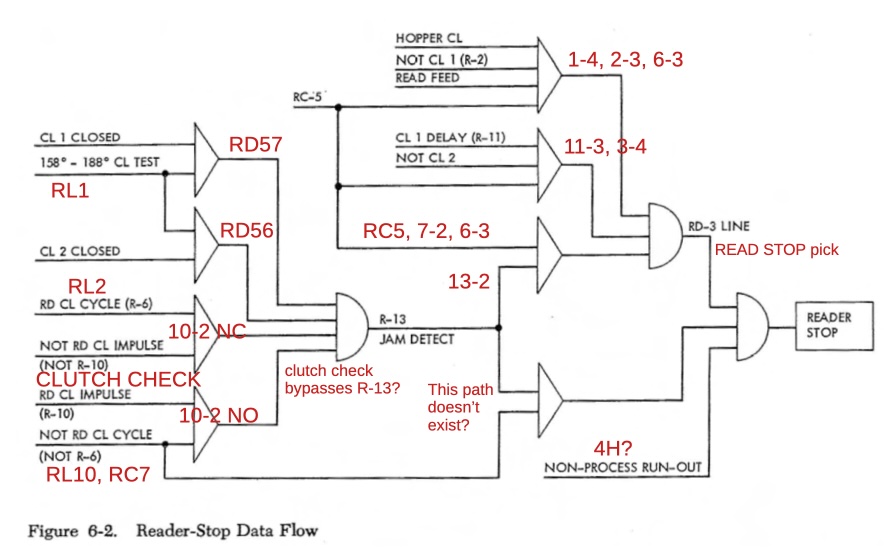
The 1402 checks that the clutch is working correctly by testing the clutched (RL) cams. In particular, during each cycle it verifies that if a clutch was requested, the clutch cycle happened. Conversely, if a clutch was not requested, the 1402 verifies that a clutch cycle did not happen. If there is a problem, a READ STOP is triggered. Relay R10 CLUTCH CHECK holds the request state. (Remember that READ STOP is generated by the 1402 for a mechanical issue, while READ CHECK is generated by the 1401 for a data error, if the two sets of brushes read different data.)
The following diagram, annotated from the CE Reference Manual shows the various paths to a READER STOP.


