This repository describes hardware and software for reverse-engineering a test box used with Apollo space hardware. This is unlike to be useful to anyone else, but I figure I'll document it.
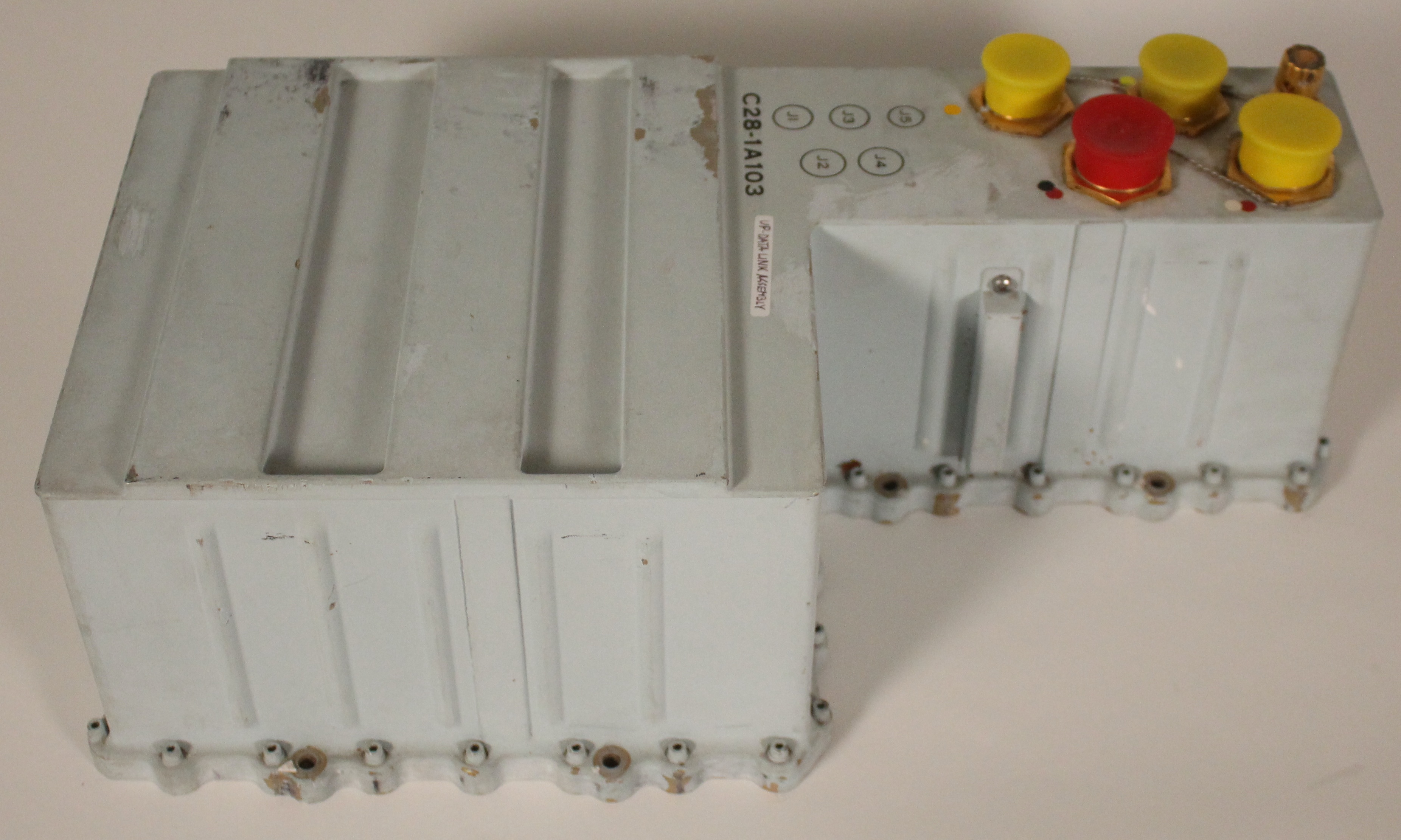
In the Apollo mission to the Moon, the Up-Data Link was used to send data up to the spacecraft from the ground.
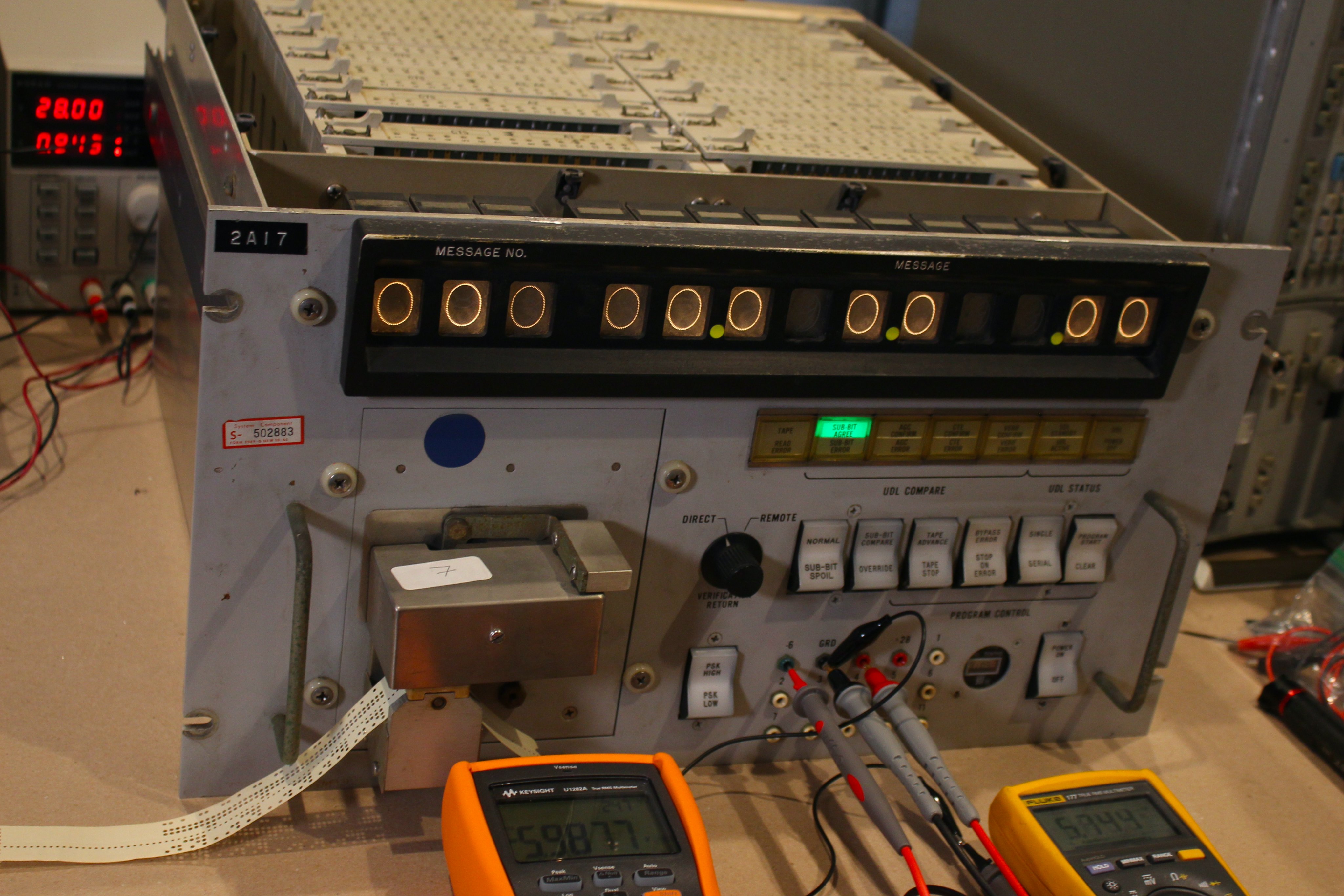
To test the Up-Data Link, the Up-Data Link Confidence Test Set was used. Unfortunately, we can't find any documentation on this test box, so I'm reverse-engineering it.
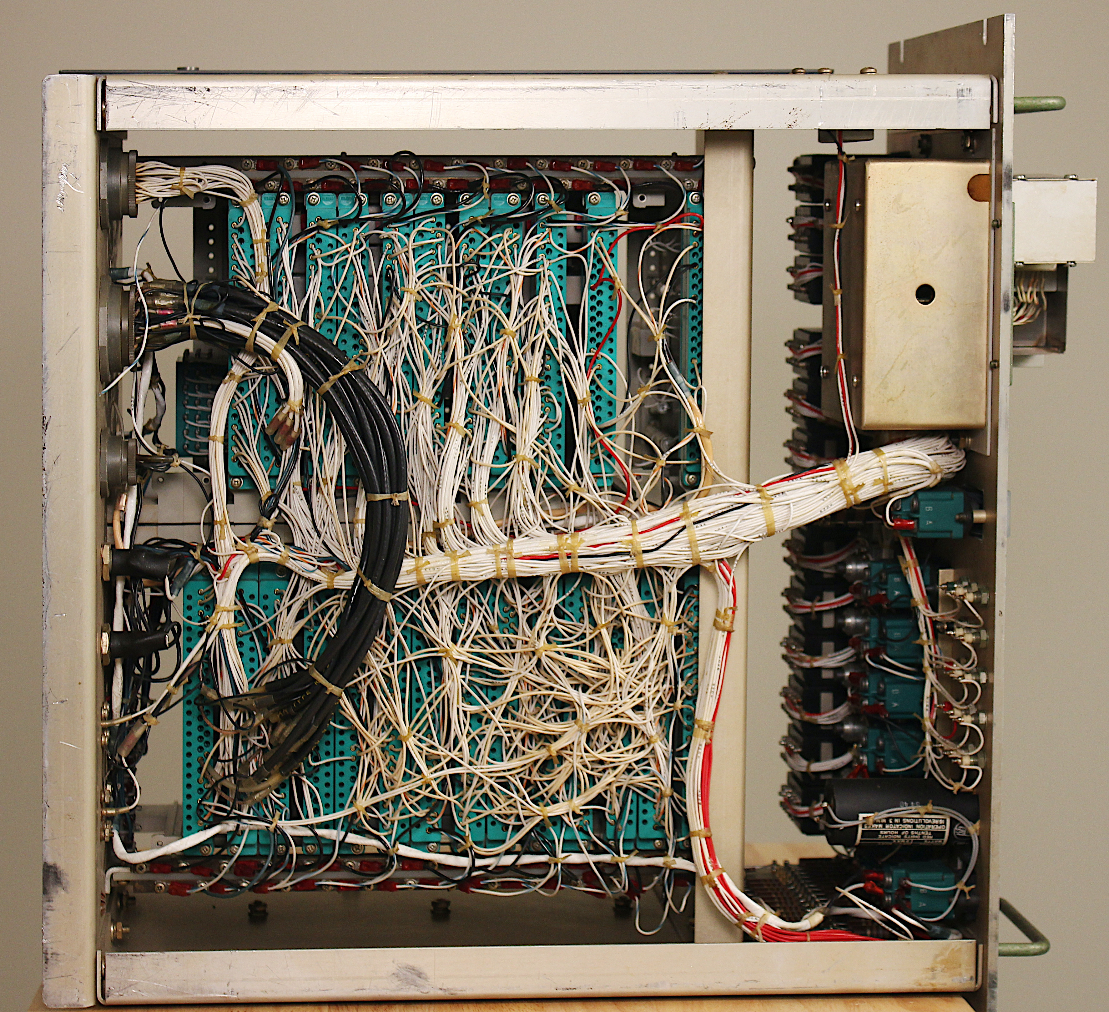
The box consists of 25 circuit boards plugged into a wire-wrapped backplane. It's almost impossible to figure out how the boards are connected through this tangle of wires. I beeped out some connections with a multimeter, but it is extremely tedious to do this manually through trial and error. So I decided to automate the beeping process.
My idea was to build two boards that will automatically beep out the connections between them. The idea is to pull one pin low and then see which other pins are pulled low on the other board; this indicates the pins are connected.
I still need to put boards into each combination of slots, so I need to run 300 scans. This is still somewhat tedious, but much better than probing the entire backplane manually to find a single connection.
The backplane is implemented with 47-pin Elco connectors. Each board has three 16-bit GPIO chips connected to these pins; I used PCA9555A chips.) The chips are driven over I2C from a Teensy microcontroller. (Thanks to PCBWay for sponsoring these boards.)
On the software side, I wrote a simple program beeper.ino, which cycles through the 47 pins on each board, pulling each pin low in turn. It reads the remaining pins to see which ones are low and outputs that data to the serial port. It takes under a second to perform this scan.
I run beeper.py on my laptop; it records the output for each scan in output files.
Finally, the program net.py processes these output files to find connected components and output the wiring nets.
I pulled out all the boards, so I don't get any interference from the circuitry. However, the power and ground connections are still wired to the filter capacitors. As a result, I see phantom connections between power and ground because of current flow through the capacitor. (This happens with multimeter beeping too.) More inconvenient, though, is that once the capacitors are charged low, they can continue to pull the ground pins low even when I'm scanning unrelated pins. This can make it appear that most pins are connected to ground. I filter this out in the software analysis.
A second problem is that the box has a lot of wiring to front panel switches, which are connected to power or ground (depending on their position). I'll need to sort out that wiring manually.


