DCC multifunction decoder for H0 locomotives
- 1 motor H-bridge output
- 3.6 A peak current
- PWM frequency configurable (1-40 kHz)
- overcurrent and temperature protected
- 10 function outputs
- 115 mA per output
- F0f, F0r, AUX1 and AUX2 are dimmable todo
- mappable to F0-F12 function keys
- DCC asymmetry can be detected (for automatic brake control) todo
- 4-layer PCB esigned in KiCAD
- fairly standard components (available from Digi-Key, Farnell, Mouser, etc...)
- hand solderable (I did it too)
- 4 debug LEDs (red, yellow, green and blue)
 |
 |
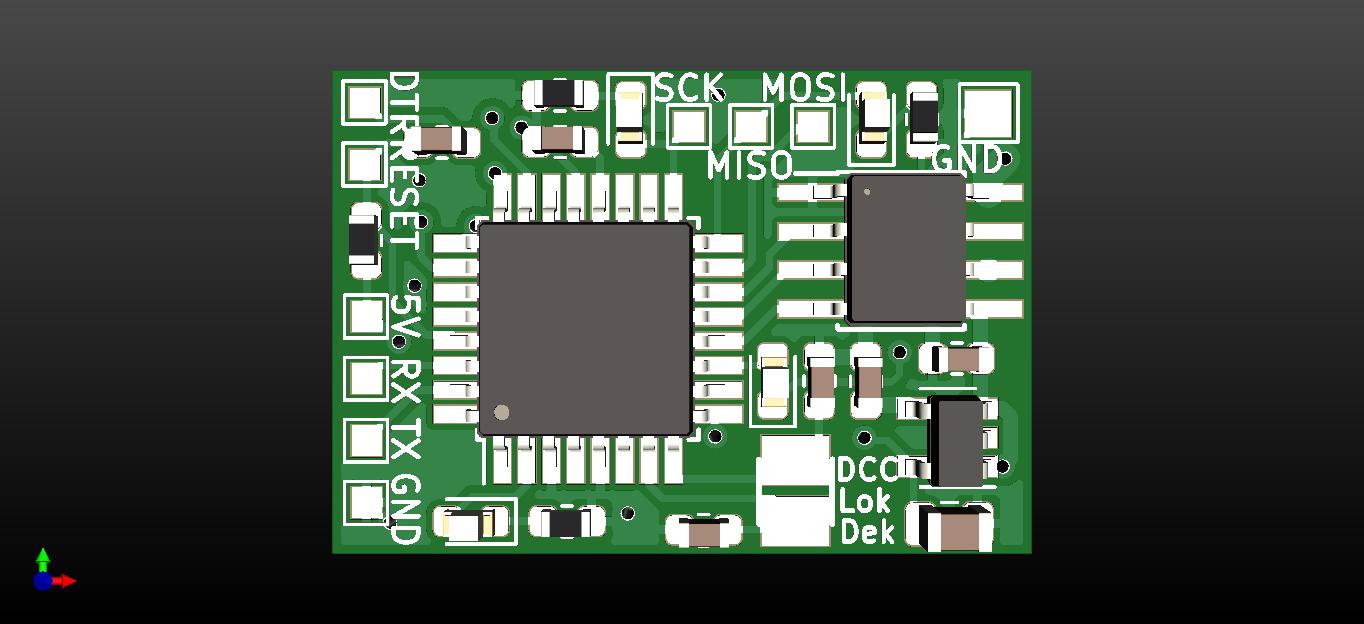
| top side |
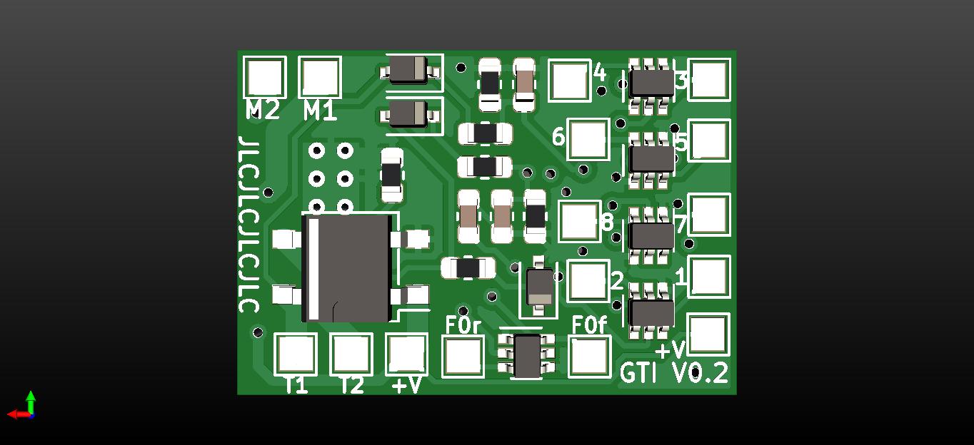
bottom side |
- Arduino compatible programming (behaves like an UNO)
- DCC decoding by NmraDcc library
 |
 |
 |
 |
 |
 |
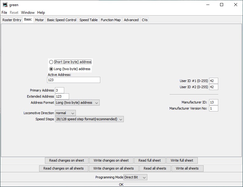
| Basic |
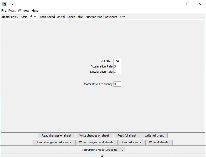
Motor |
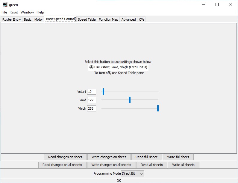
Basic speed control |
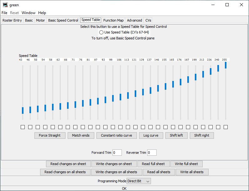
Speed table |
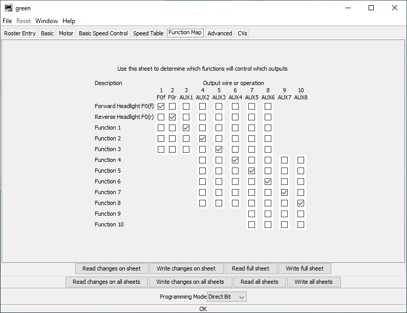
Function map |
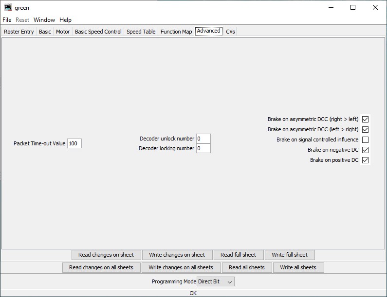
Advanced |
- Get the PCB (e.g. JLCPCB) and the components (e.g. mouser, digikey)
- Solder the components. The SOIC with exposed pad is a bit tricky, it can be soldered from the other side with a big tip and a lot of flux.
- Install the Arduino bootloader using the pads 5V, GND, SCK, MISO, MOSI, RST and an Arduino. Arduino as ISP
- Uncomment the line
#define RESET_FACTORY_DEFAULTS to fill the EEPROM with the default CV values
- Upload the code using the pads 5V, GND, RX, TX, DTR and a USB TTL UART cable like this
- Re-comment the line
#define RESET_FACTORY_DEFAULTS to avoid resetting to factory defaults every time.
- Upload the code again.
- Add the decoder XML file to JMRI. In DecoderPro select "File-> Import Decoder File..." and browse to the decoder XML. It will take some time, then adds the decoder definition to the database.
- Connect the T1 and T2 pads to the programming track of your DCC system.
- Add new locomotive with the "New Loco" button and then "Read type from decoder". It should detect the correct type:
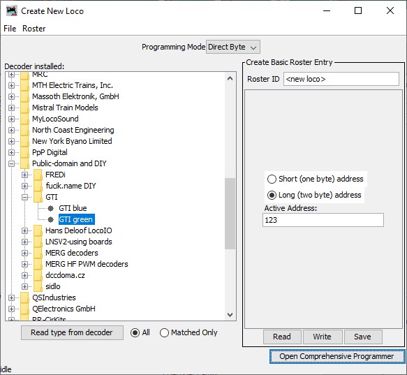
- If everything is fine, you can install the decoder into your locomotive!
| Pad |
Function |
| M1 |
Motor 1 |
| M2 |
Motor 2 |
| T1 |
Track 1 |
| T2 |
Track 2 |
| V+ |
Positive common for function outputs (keep-alive capacitor positive) |
| F0f |
F0 function output forward (open drain) |
| F0r |
F0 function output reverse (open drain) |
| 1-8 |
AUX function output n (open drain) |
| 5V |
internal microcontroller +5V supply |
| GND |
ground (keep alive capacitor negative) |
| SCK |
ISP programming clock (connect to ISP SCK) |
| MISO |
ISP programming read (connect to ISP MISO) |
| MOSI |
ISP programming write (connect to ISP MOSI) |
| RST |
ISP programming reset (connect to ISP reset output) |
| RX |
serial programming receive (connect to TTL UART TX) |
| TX |
serial programming transmit (connect to TTL UART RX) |
| DTR |
serial programming reset through a 100 nF capacitor (connect to TTL UART DTR) |


