 |
 Hardware Modules |
|
Whatever the crop, balancing yield and quality against cost and time mandates tight control of growing conditions. However, such control cannot be achieved without an intimate knowledge of the growing environment, demanding measurement, processing, data-logging, display, control and communication sub-systems for which the low-cost ESP32 and ESP8266 devices are very well suited. This document identfies experimental hardware and software elements employed at various points in the project over an extended period. Photographs of prototype hardware, screenshots of typical database output, WEB pages, control/monitoring GUIs and code listings are presented (with attributions where appropriate). Whilst these elements are valid in their own right they are illustrative only and it should not be assumed that they are either complete or directly relateable. However, I would be delighted to provide any further explanatory information on request. |
Contact Stuart A Spray C.Eng MIEE
| The system structure is based on a star/hub network, each host (e.g. greenhouse/polytunnel) being equipped with its own data acquisition, communications and optional control capabilities. Hosts within WiFi range (local hosts) communicate directly with the hub via WiFi protocols whilst those beyond WiFi range (remote hosts) report to a central hub using low-power wide-area network LPWAN/LoRa protocols. It should be noted that the ESP32 series of microcontrollers provide all the necessary LPWAN and WiFi hardware and software so are particuularly well suited to this application, distances of 1 - 10 kM being regularly achievable. The hub acts as a gateway providing an internet path via a WiFi router (landline or wireless) to an SQL database server where all host-originated parametric measurements are consolidated and available for off-line analytical purposes. |
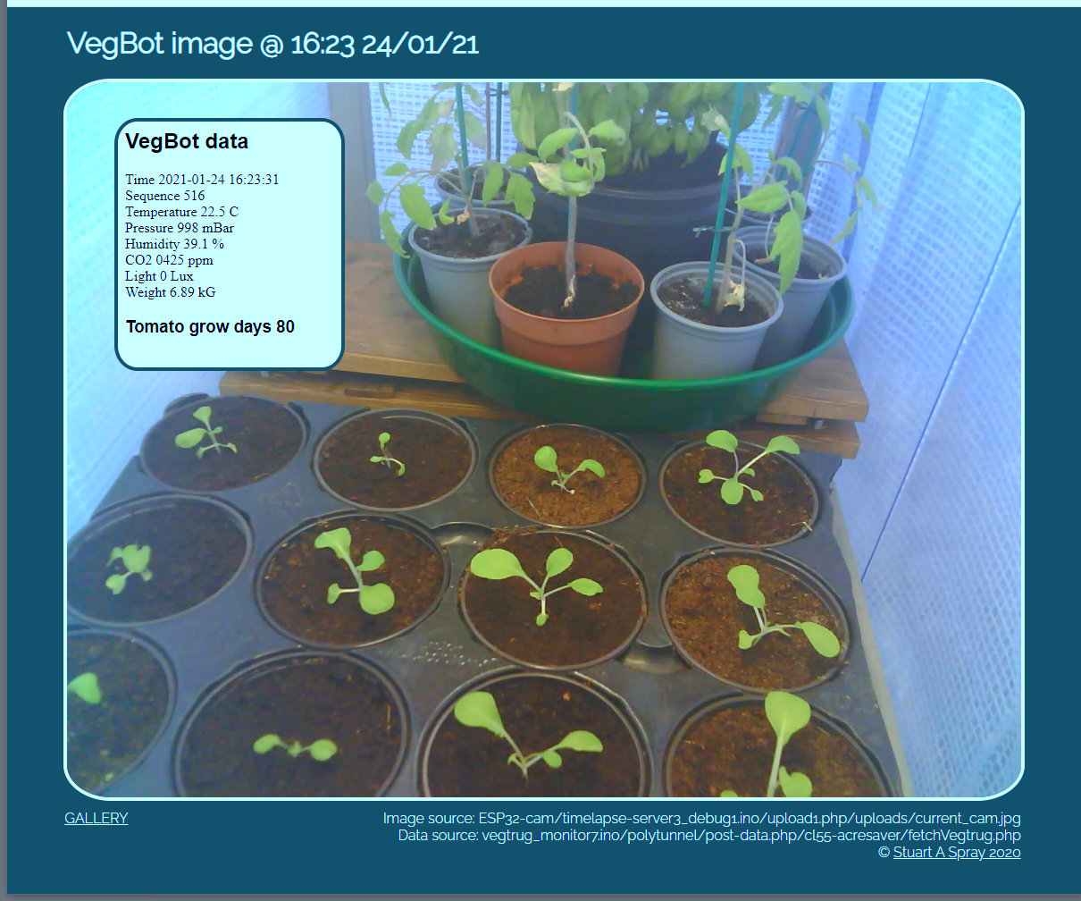
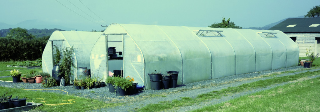
| For the purpose of this project and with the cooperation of a local tomato grower having polytunnels scattered over many hectares, a field operation was set up so that selected tunnels could be set up with appropriate monitoring and communication equipment. To conveniently facilitate local off-site R&D for this project a small greenhouse 'lab' was constructed (the 'VegBot'), described in the related ESP32 R&D Lab repository. |
| An example on-site polytunnel and outbuiding |
|---|
 |
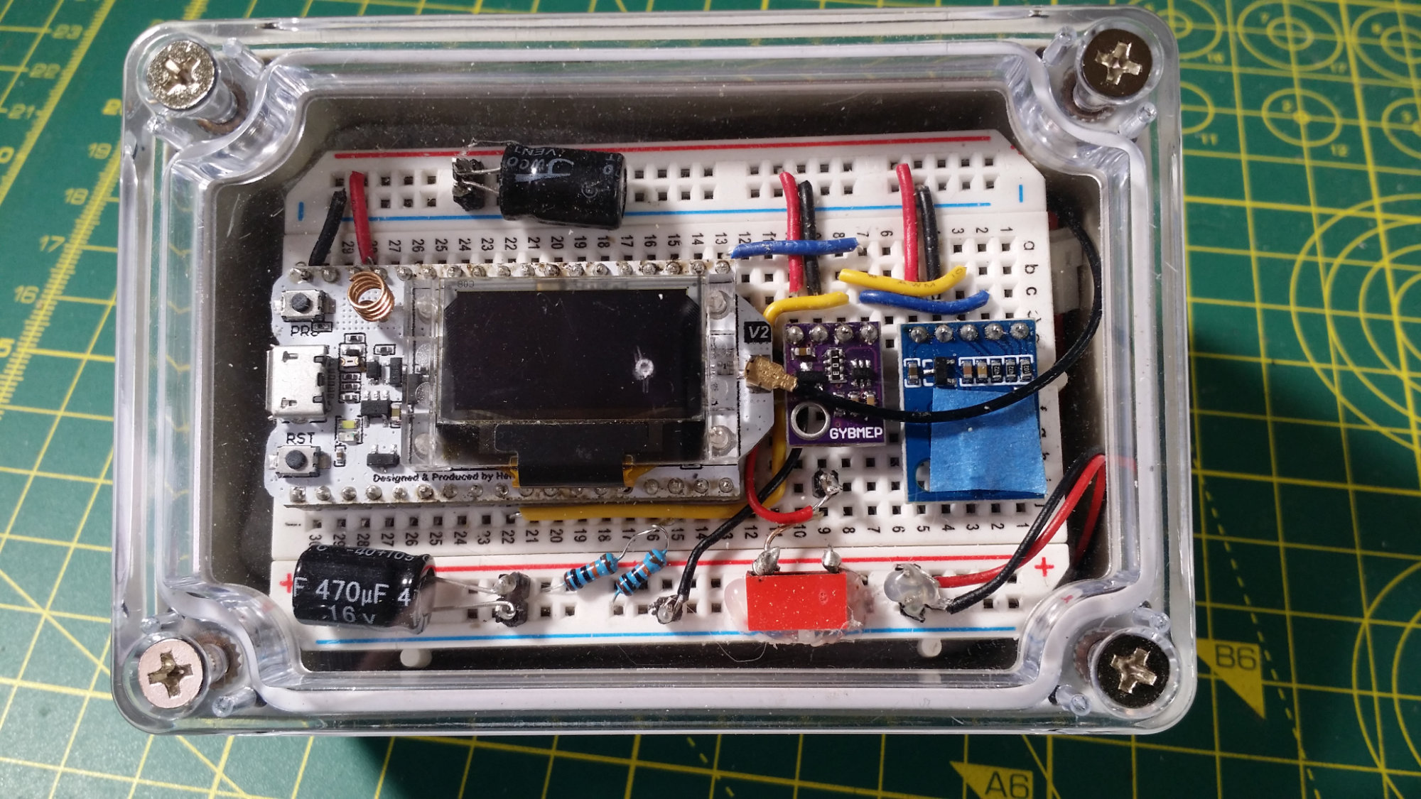
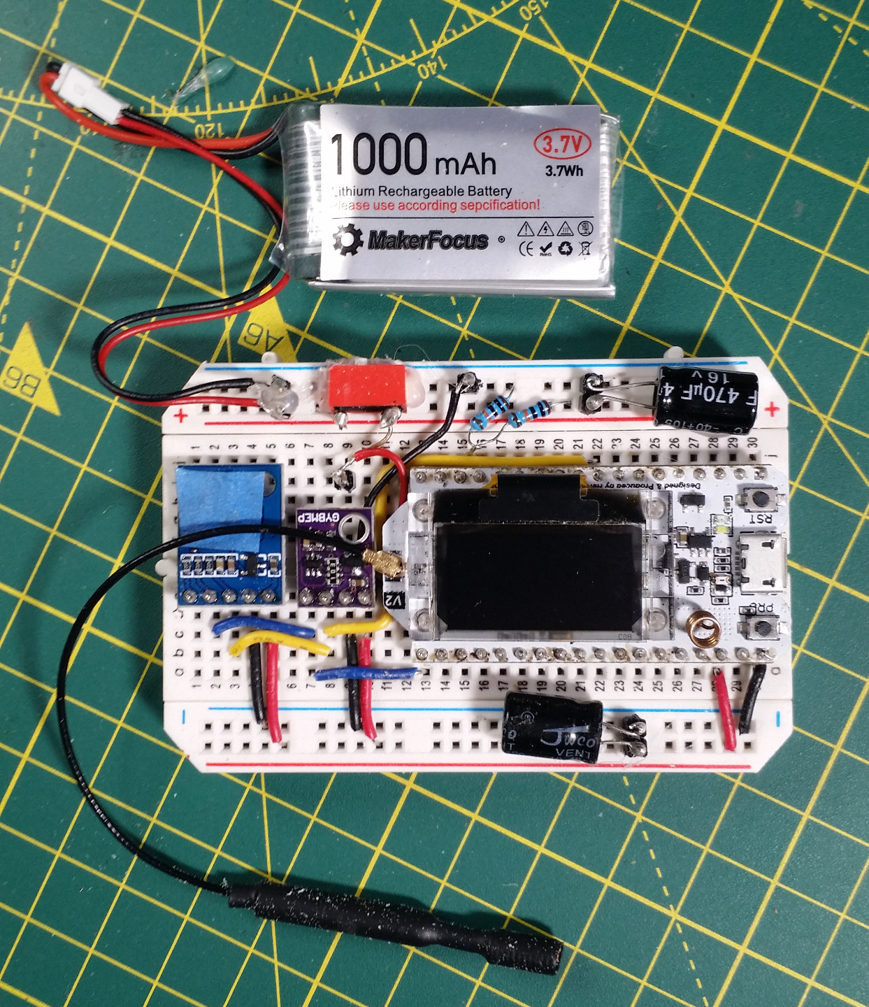
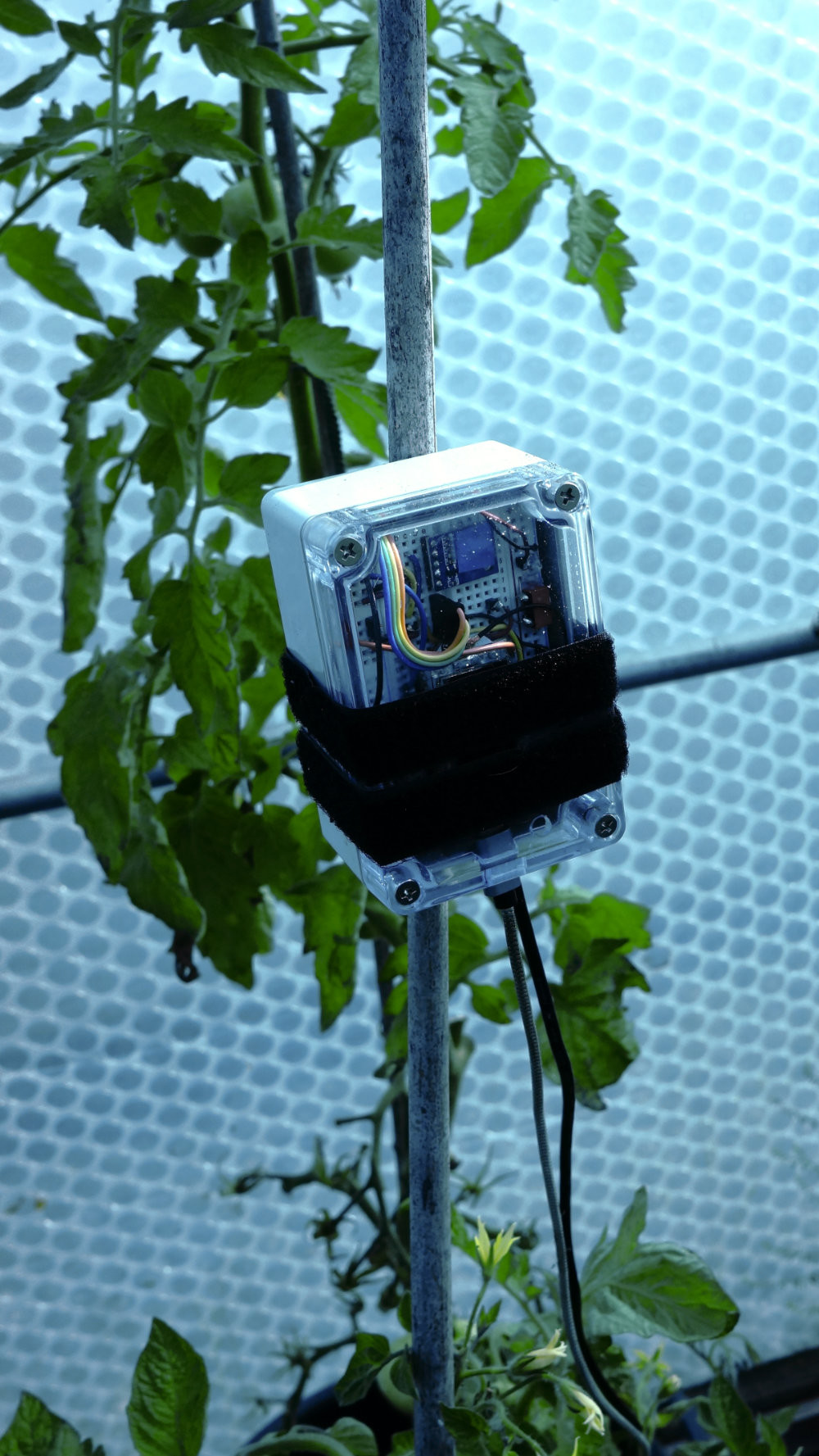
| A Remote Host | Internal |
|---|---|
 |
 |
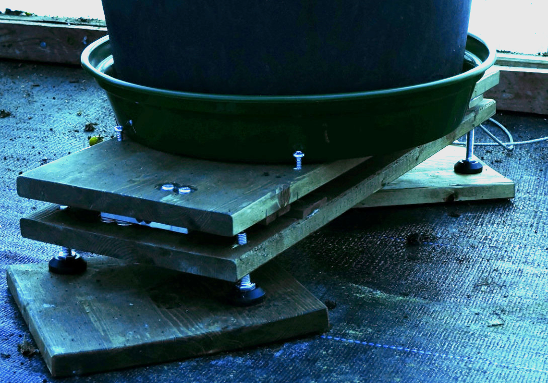
| In-situ | Load cell platform |
 |
|
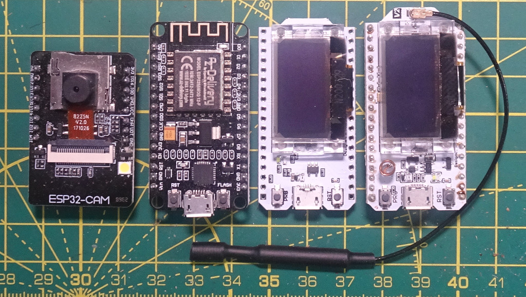
| This module adopts a Heltec WiFi LoRa 32 (V2) microcontroller running two cores at 240MHz with 8Mb flash and 320kb RAM. It has a self-contained micro-USB serial port for uploading and may be used under either the Espressif IoT Development or Arduino frameworks. Power management is on-board (can interface directly with a LiPo) and communicates via conventional WiFi and LoRa at 868MHz. 30+ GPIO pins are available with I2C/SPI busses. Its 128x64 OLED display is redundant for this module. The primary purpose of this module is to acquire temperature, relative humidity, light, atmospheric pressure and weight measurements, assemble the data into packets and transmit them over a LoRa link to its receiver counterpart at the gateway. The loadcell platform uses a pair of 10kG strain guages linked to a bridge amplifier and 16-bit ADC via an I2C bus. One of the strain guages can just be seen in the photograph, sandwiched between the upper and lower platforms, the jack screws being used for levelling purposes. See code here | |
| LoRa Receiver and Gateway Module..... | ..... Internal |
 |
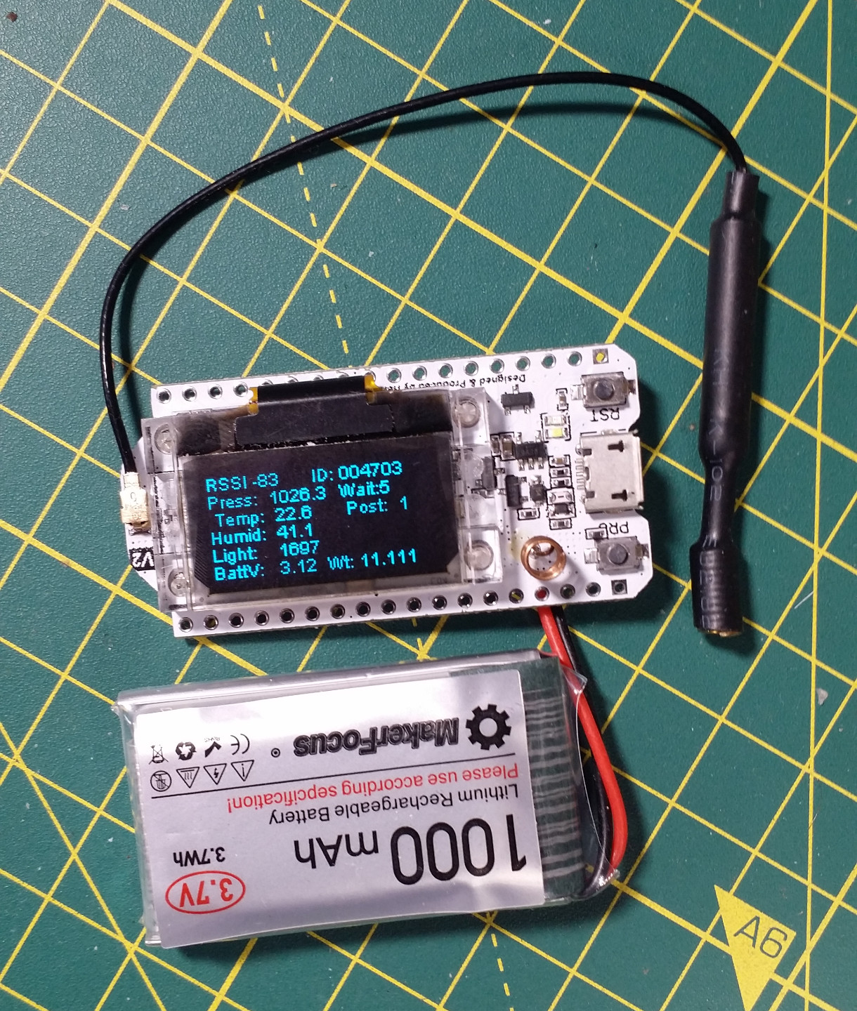 |
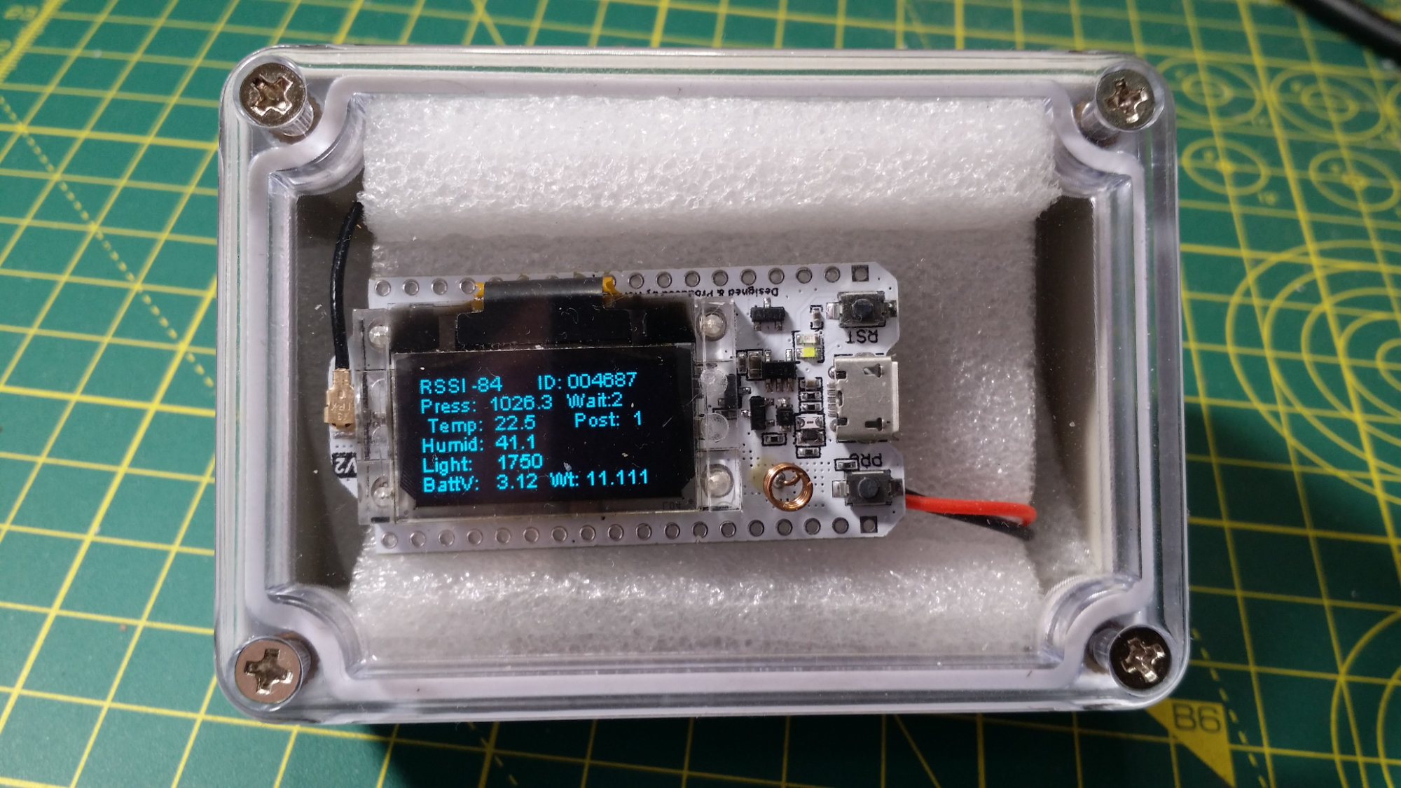
| This module uses the same hardware as the corresponding transmitter, but without the transducers and utilising the OLED display and WiFi capability. It acts as a Gateway to an SQL database server by receiving data packets over the LoRa link from the transmitter and forwarding them via a WiFi client connection to a local Internet Router (landline or Wireless 4/5G). Visible on the OLED display are the temperature, pressure, humidity, light and weight measurements as well as some supervisory data including the RSSI (Radio Signal Strength Indicator), Battery voltage, Message ID (a transmitter generated serial number to identify missing packets), a 'Wait' countdown timer to indicate system activity and a 'Post' counter to indicate the number of previous attempts to post the message. (an indicator of link quality). See code here. | |
| A Local Host | |
|---|---|
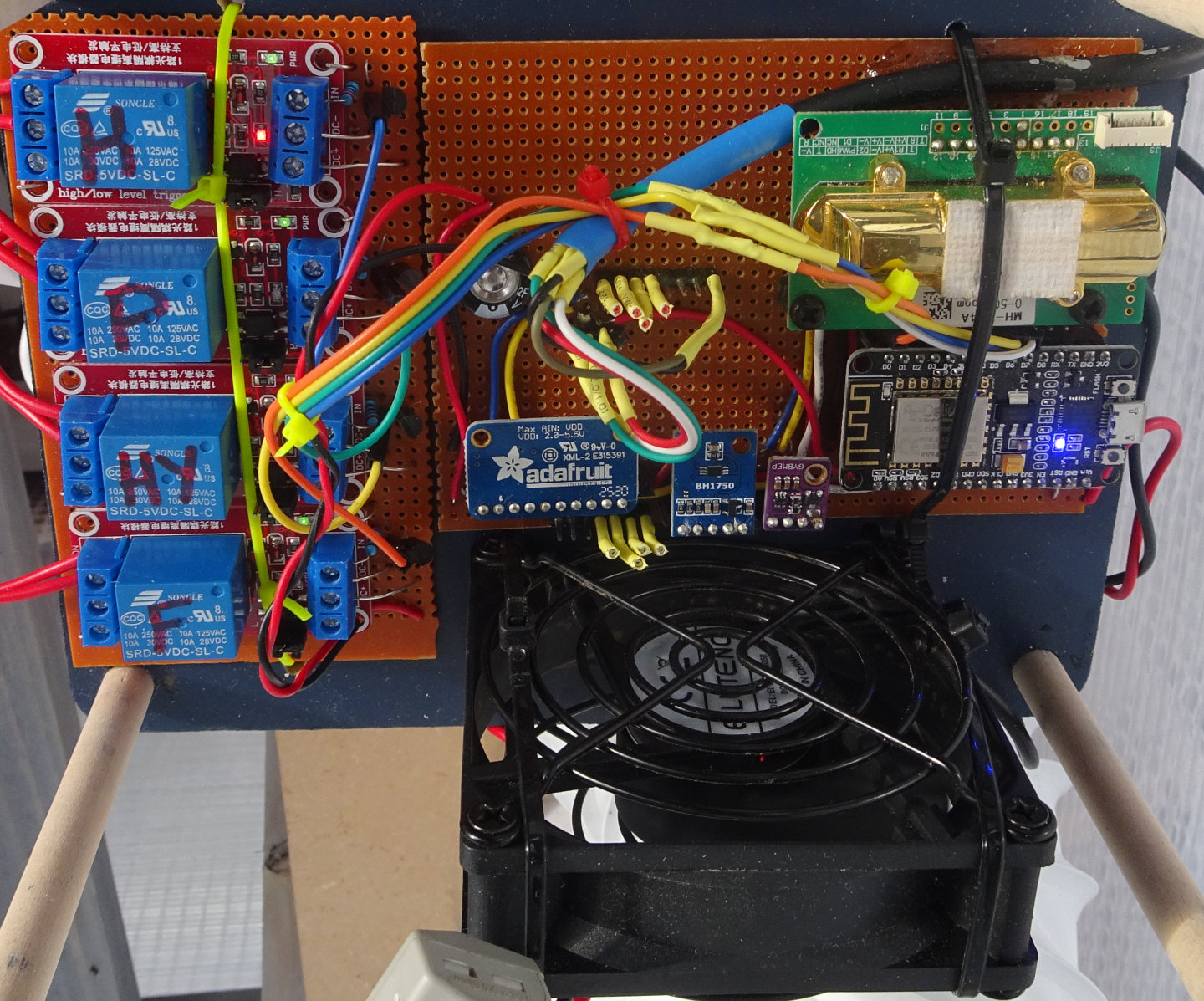 | |
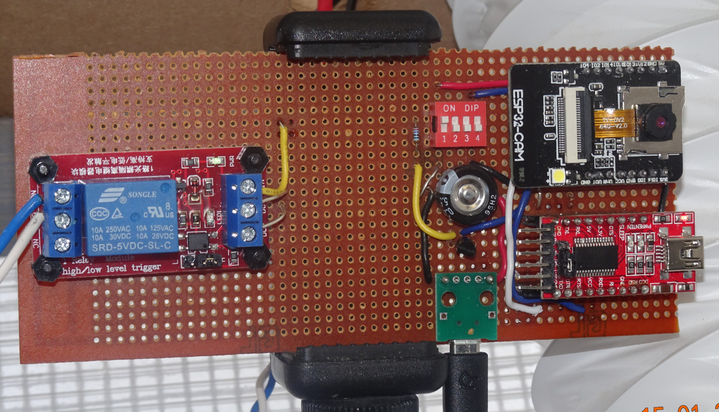
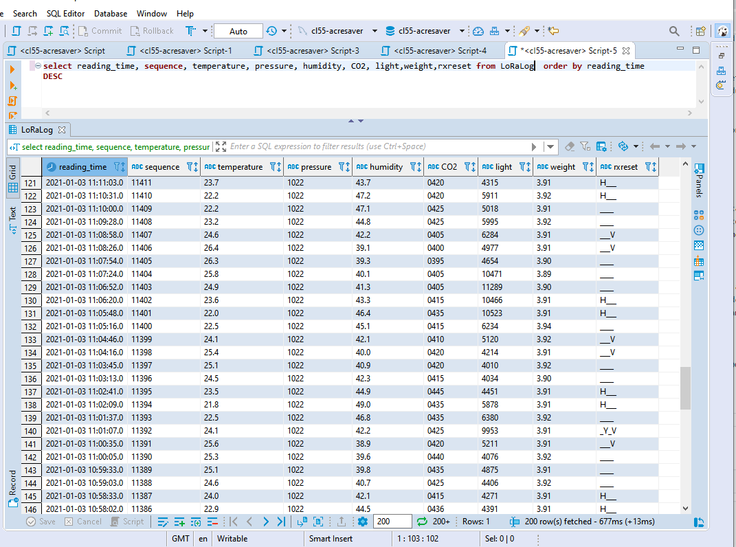
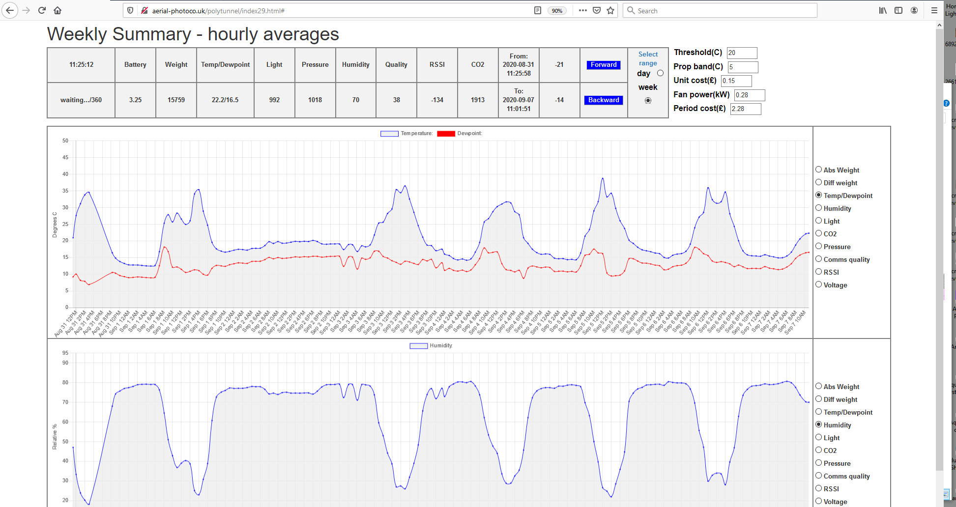
| The local host is based on a single NodeMCU ESP8266 acquiring temperature, relative humidity, atmospheric pressure, light and weight via a I2C bus. CO2 measurements are made by interrupt driven PWM techniques. (See MHZ-14-PWM-by-Interrupt repository). It might seem strange to be measuring weight but this parameter is used as an analogue of water content/dryness of the growing medium and thus a convenient way of controlling irrigation via the pump control loop. The fan ensures that the transducers are flooded with ambient air and not just responding to local board conditions. Load cell noise reduction of the weight measurement is carried out by digital filtering techniques (see code listings Loadcell-Cleaning-the-output repository. Sub-optimal Bang-bang control loops are provided for temperature, humidity, weight (pump control) and ventilation, their outputs being interfaced by low-power isolating relays. The relays are interfaced to the ESP8266 output ports via 2n3904 NPN emitter followers (Historical note: 2n3904s have been around since the late 60's!) The WEB server component of the ESP8266 generates an interactive monitoring and control GUI on the local WiFi network (see code here ), uploading parametric measurements via a PHP interface (code here ) to a public SQL server (see sample database data list below left). SQL data is subsequently accessed offline via a PHP page (see code) for analytical purposes and to form the basis of various javascript-driven charts: see example output below right and page-code listing here. | Local Host GUI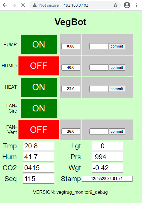 CAUTION! Whilst the ESP32/8266 microntroller is fully capable of delivering all the services in this module, due consideration should be given to their potential disruptive mutual interactions. For example, the WEB server GUI may be stimulated into activity by a client connexion at any arbitrary time, just when one of the control loops is commanded into action by a transducer measurement. The outcome may be quite benign but is at the very least unpredictable and at worst may cause a system hangup or dangerous output. This has been an observed condition in this module and warrants a better design approach such as real-time task scheduling such as found in FreeRTOS. Further work is required here. |
| Sample SQL data | Sample derived chart |
 |
 |
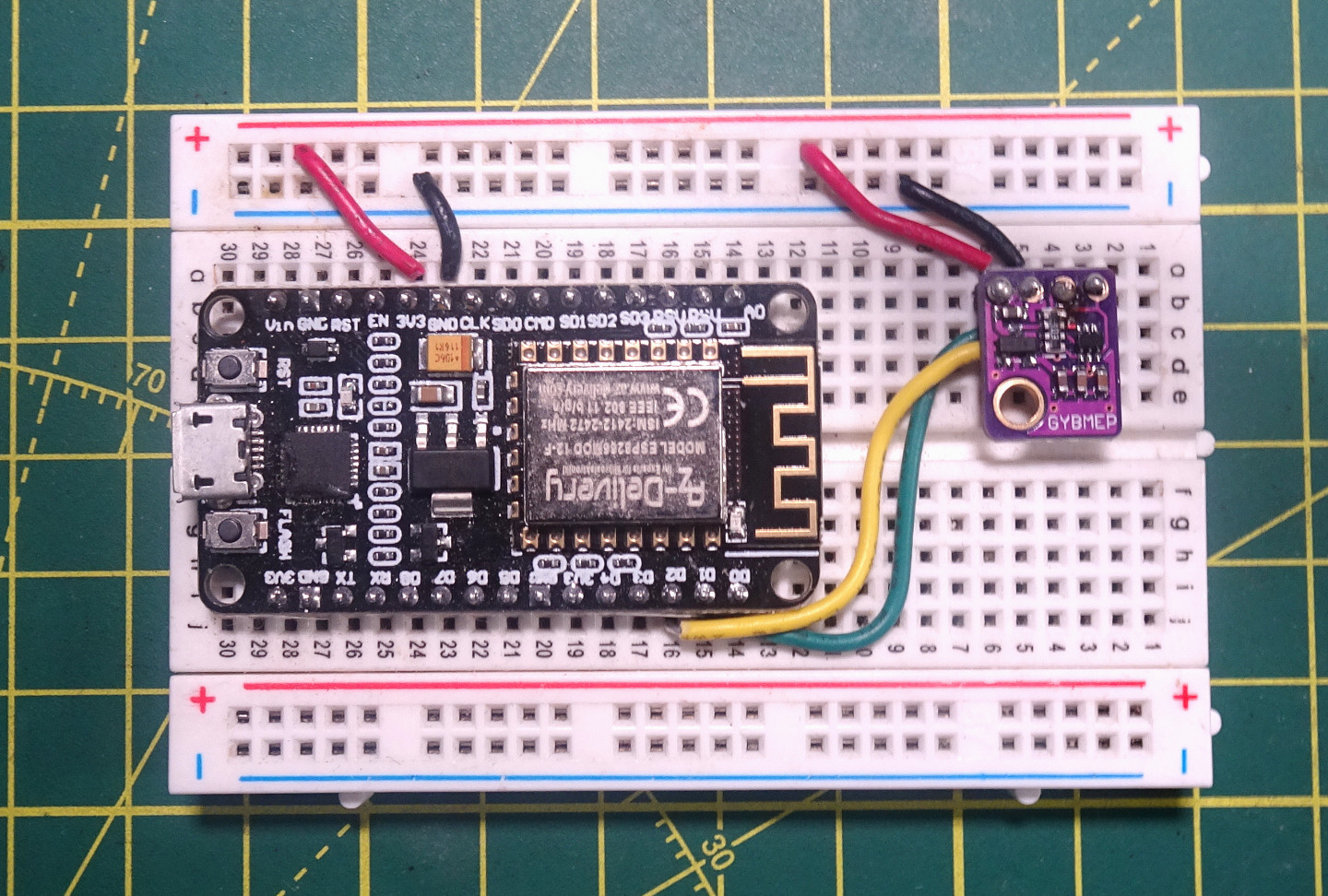
| A simple stand-alone temperature/humidity/pressure/WEB server module | Stand-alone WEB page |
|---|---|
 |
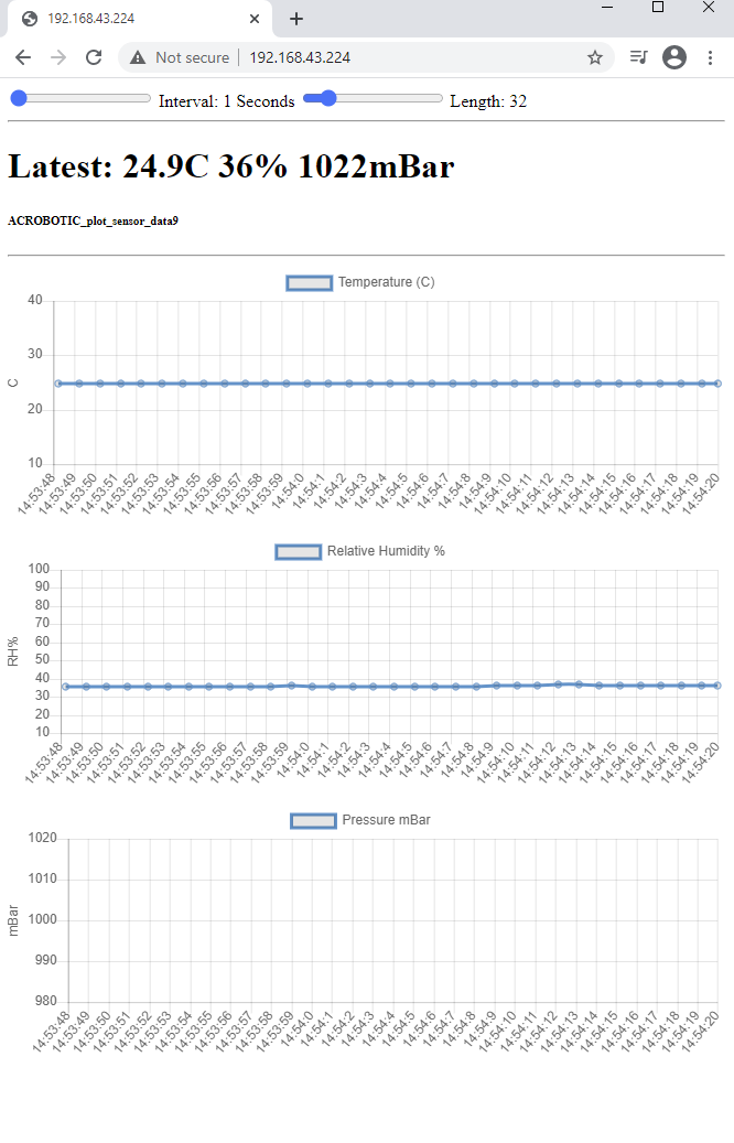 |
| This is about the simplest stand-alone ESP8266 environmental monitor which uses the BMP280 multi-transducer device on an I2C bus. It acts as a WEB server on the local network, generating time-based graphical data of Temperature, Relative Humidity and Pressure. By adopting web-socket protocols, complete re-writes of the page after each data update are avoided resulting in a smooth glitch free display. See code here.The blank pressure graph is due to the fact that at the time of publication the pressure was off-scale! | |
| A data display module | |
|---|---|
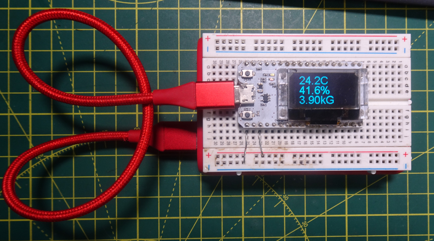 |
However a WEB page is originated, the raw data embedded within its HTML code can always be extracted and represented differently. For example, the raw data embedded in the above WEB page can be analysed or 'scraped' so as to make it available through an alternative interface. The Heltec WiFi kit 32 (seen left atop a 'PowerAdd' battery) with its on-board 128x64 OLED display is a suitable candidate for the application of this technique, where selected parameters are 'scraped' from the HTML code (which contains more than just the BMP280 data) and represented directly on the display. The particular beauty here lies in its simplicity of hardware: the ESP32 being the only component required. See code here |
