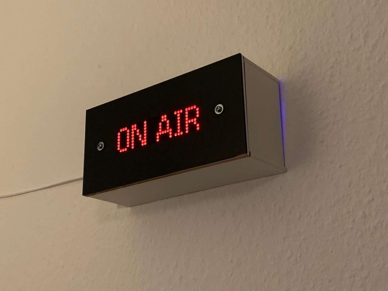
I wanted an "On Air" sign that would show up behind me while I'm in a video call at work.
Since I work from home in the living room, this is a useful indicator to my wife that I'm in a meeting (even if muted and just listening). It's also something fun that shows up behind me while in a call and gets many nice compliments!
- "On Air" status must be triggered automatically when Zoom calls begin or end
- Learn some basic woodworking skills
- Make the finished product look minimal and stylish
- Learn how to use an RTC (Real-time clock) module
- Include multiple modes so the project can be interacted with
Electronics:
- NodeMCU v3 ESP8266 microcontroller board
- 8x32 LED matrix
- DS3231 Real-time clock module
- Cables
- Breadboard
- A long USB cable
Case:
- 3mm darkened perspex / acrylic
- Nuts and bolts
- 6mm MDF board (sourced from leftover IKEA shelving)
Tools:
- Jigsaw
- Clamps
- Wood glue
- Jigsaw table
- Drill
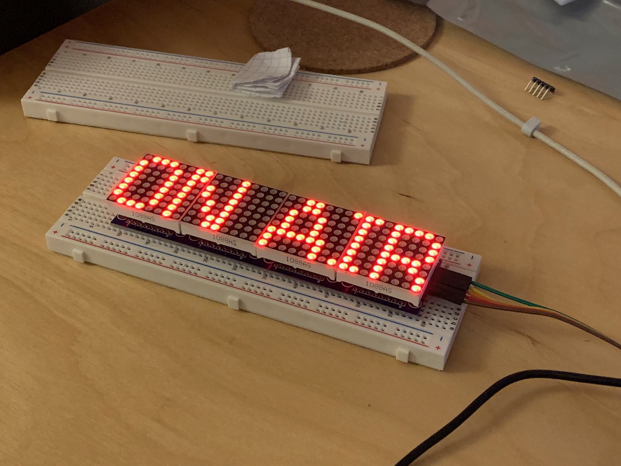 Prototyping the electronics came first, as usual. I hadn't worked with a large LED pixel array before, so this was the first thing I wanted to get right. With the
 LedControl library this is actually quite easy!
I was inspired by this design which took an old wine box and converted it into an 8x64 LED display.
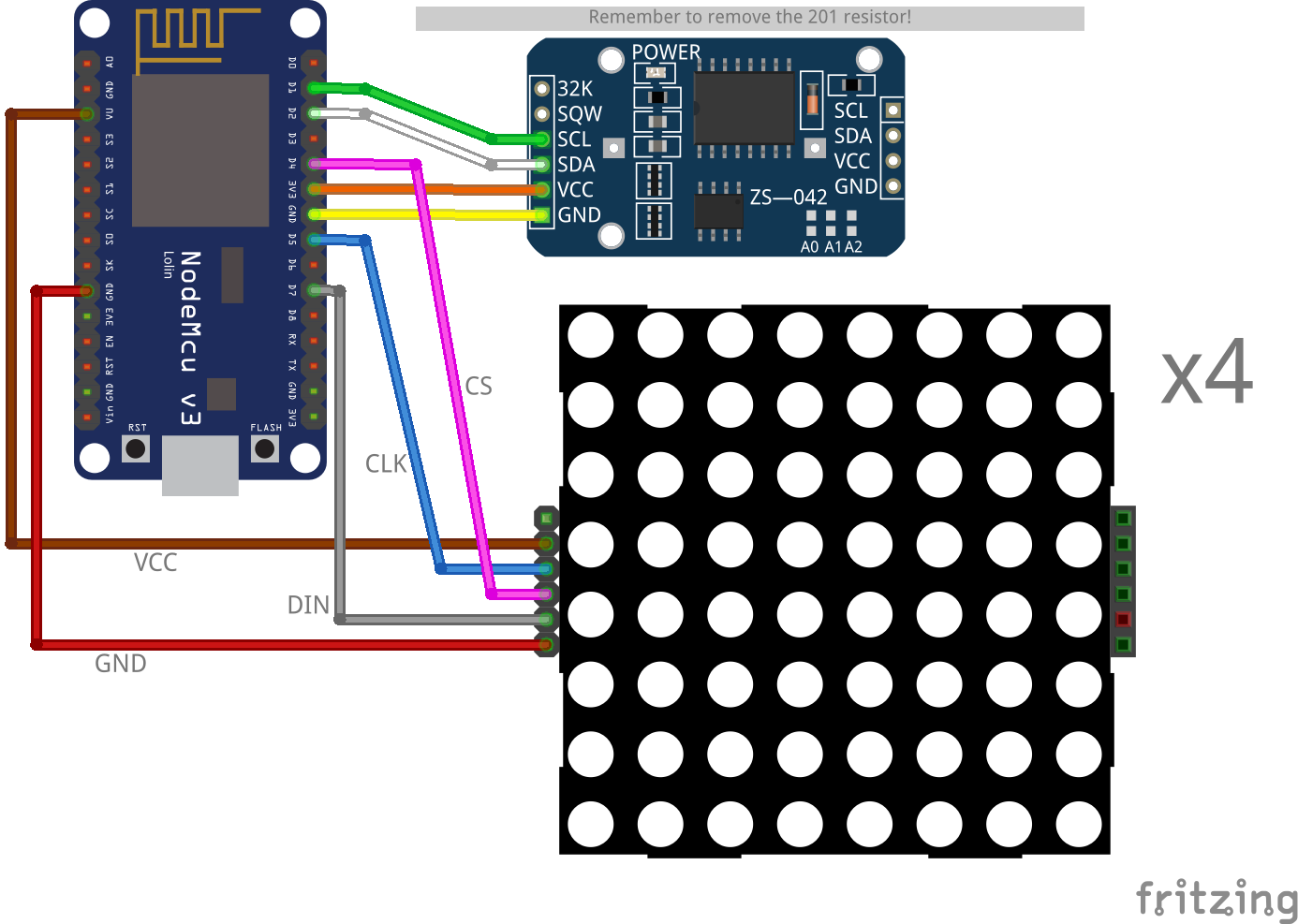
Beyond the cliché "ON AIR" message, I also wanted a couple of other modes to be available. As this is a wall piece that'll be visible from the whole room, a clock mode seemed obvious. That meant testing out the DS3231 RTC module. It turns out (!) that lots of DS3231 modules available online ship with a flaw that puts the battery at risk of overcharging and possible explosion. However, desoldering a resistor will safely avoid this risk.
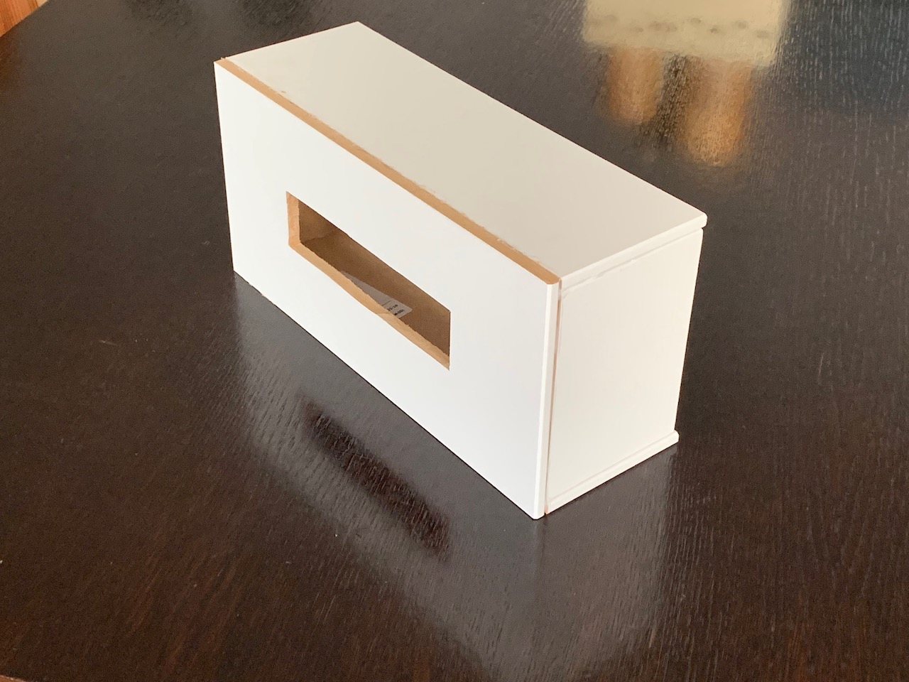 The case is made from pieces of 6mm MDF that were "upcycled" from leftover IKEA shelving. Each piece was measured and drawn out, then cut with a household jigsaw tool. Videos like this were really helpful for me to know how where to get started with it.
After cutting the pieces, and cutting out the front slot for the LED's, I applied wood glue and clamped the sides together. Some heavy weight from above helped to keep the sides stuck on to the front. I left the glue to cure for about 24 hours.
Next, I checked that the LED's fit correctly and snugly into the front slot. They did!
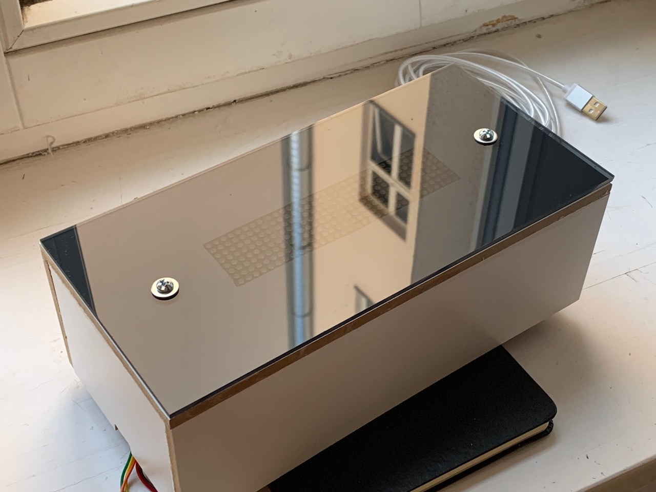 The acrylic front cover came with protective plastic on both sides. Leaving this on, I carefully drilled through the acrylic to leave a clean cut on both sides. Separately I drilled through the front cover in the same location. After confirming the alignment, I removed the acrylic's protective cover and bolted it to the case, with some washers to distribute the force a little better. It's a snug fit but doesn't need to be too tight.
Final dimensions:
- 250mm wide
- 89mm deep (86mm case + 3mm acrylic)
- 120mm tall
- LED slot
- 130mm wide
- 32mm tall
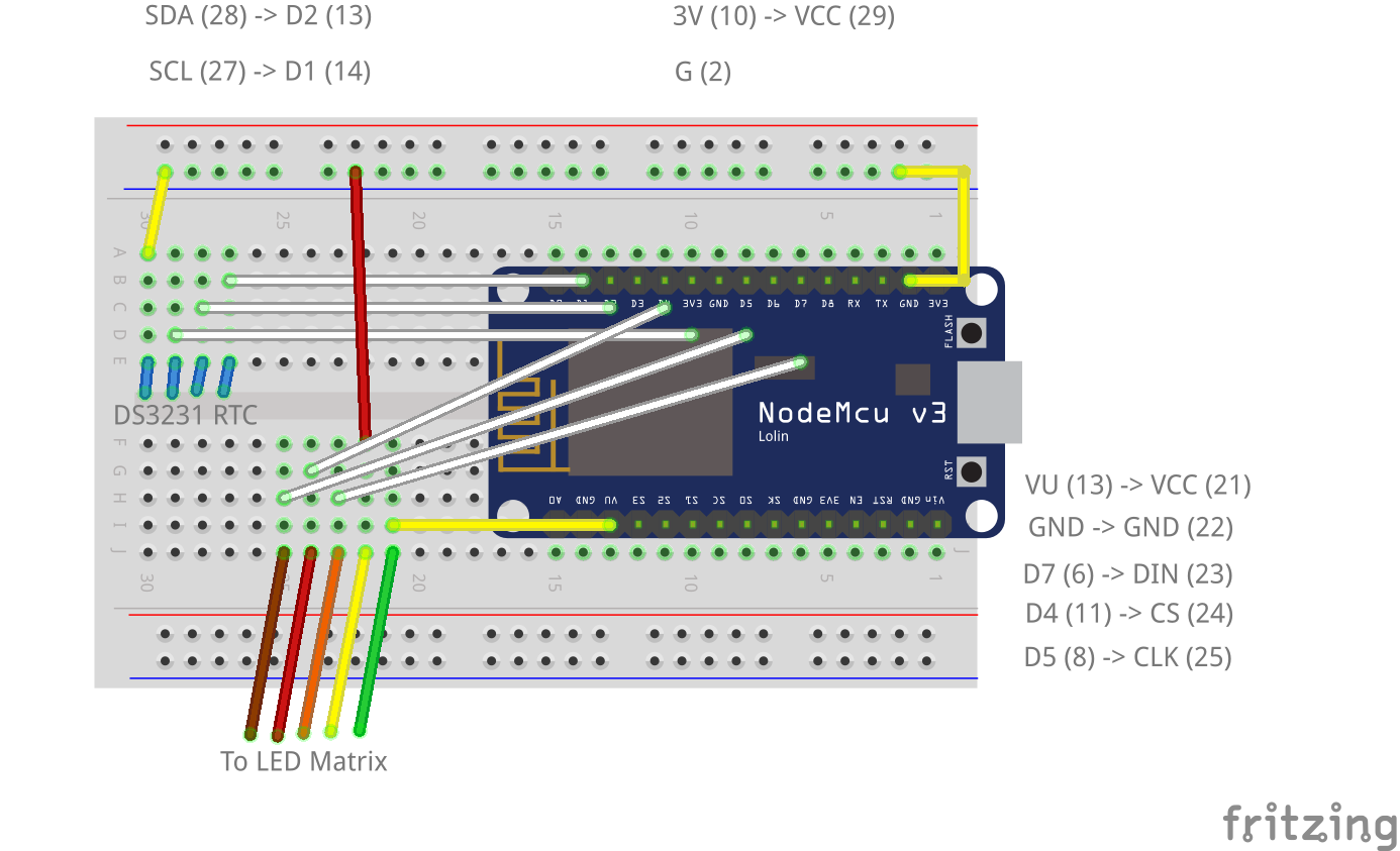
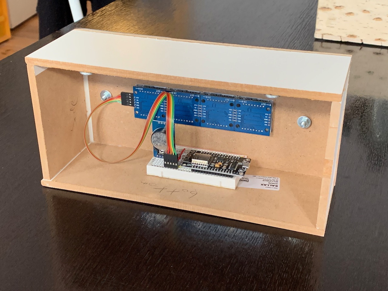
Everything is mounted on a breadboard and wired to that. There's plenty of space left inside the case - in fact it could be slimmer, if I was to build another version in the future.
Component layout: image generated from fritzing fileBreadboard layout: image generated from fritzing file
The microcontroller board is USB powered, plugged into a wall adaptor.
Breadboard and screen installed inside the boxThe program operates on a single loop, following this workflow:
Generated from .puml fileSee the Swagger docs for details
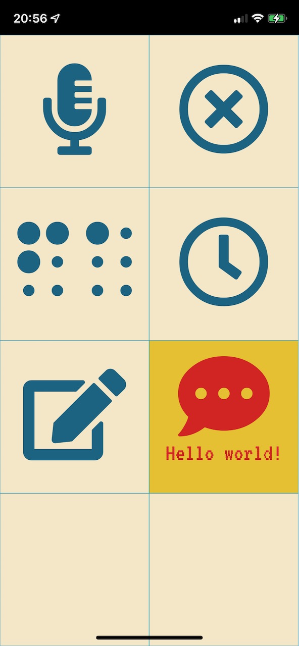 I based the design for the remote control application on the one I made for my traffic light. It's pure JS/CSS with the only external dependency on FontAwesome for icons.
It's hosted on GitHub pages so all the on-air sign has to do is proxy the initial request to load index.html
Updates to the sign state are shared via Websocket to all connected clients. Requests to change state are provided by the REST endpoints mentioned above.
Originally I wanted to use Zoom's webhook API to send messages to a gateway API, and then pass these on to the on-air sign. However, it turned out to be easier to use the fantastic pyzoomproc utility, which runs on my work laptop and triggers curl to hit the appropriate endpoints on my sign.
Everyone's #1 feature request: <marquee/> support. From the webapp or using the /api/message endpoint, you can send a message that will be displayed and scroll on the screen.
Current limitations:
- Non-accented ASCII characters only
- 255 character max length
The RTC module keeps time quite accurately, to within a few seconds over a year. I used a separate Arduino sketch to set the UTC time correctly once, and then I rely on the Timezone library to handle local time conversions. This also conveniently handles daylight savings time adjustments.
As the RTC module also includes a thermometer, the current temperature can also be displayed on-screen. I made a small correction because the sensor is in a closed box and doesn't get much airflow, but it seems to be fairly accurate for "room temperature" values.
Some future ideas:
- Include a QR code on the webapp for sharing easily
