CAN-BUS is a common industrial bus because of its long travel distance, medium communication speed and high reliability. It is commonly found on modern machine tools and as an automotive diagnostic bus. This CAN-BUS Shield gives your Arduino/Seeeduino CAN-BUS capability. With an OBD-II converter cable added on and the OBD-II library imported, you are ready to build an onboard diagnostic device or data logger.
- Implements CAN V2.0B at up to 1 Mb/s
- SPI Interface up to 10 MHz
- Standard (11 bit) and extended (29 bit) data and remote frames
- Two receive buffers with prioritized message storage
Contents:
The following code samples uses the CAN-BUS Shield, wired up as shown:
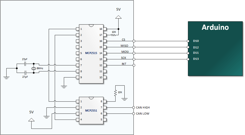
If you want to make your own CAN board for under $10, you can achieve that with something like this:
Component References:
- MCP2515 Stand-Alone CAN Controller with SPI Interface
- MCP2551 High-speed CAN Transceiver - pictured above, however "not recommended for new designs"
- MCP2562 High-speed CAN Transceiver with Standby Mode and VIO Pin - an updated tranceiver since the MCP2551 (requires different wiring, read datasheet for example, also here)
- TJA1055 Fault-tolerant low speed CAN Transceiver. Mostly used in vehicles.
- Download the ZIP file from https://github.com/autowp/arduino-mcp2515/archive/master.zip
- From the Arduino IDE: Sketch -> Include Library... -> Add .ZIP Library...
- Restart the Arduino IDE to see the new "mcp2515" library with examples
To create connection with MCP2515 provide pin number where SPI CS is connected (10 by default), baudrate and mode
The available modes are listed as follows:
mcp2515.setNormalMode();
mcp2515.setLoopbackMode();
mcp2515.setListenOnlyMode();
The available baudrates are listed as follows:
enum CAN_SPEED {
    CAN_5KBPS,
    CAN_10KBPS,
    CAN_20KBPS,
    CAN_31K25BPS,
    CAN_33KBPS,
    CAN_40KBPS,
    CAN_50KBPS,
    CAN_80KBPS,
    CAN_83K3BPS,
    CAN_95KBPS,
    CAN_100KBPS,
    CAN_125KBPS,
    CAN_200KBPS,
    CAN_250KBPS,
    CAN_500KBPS,
    CAN_1000KBPS
};
Example of initialization
MCP2515 mcp2515(10);
mcp2515.reset();
mcp2515.setBitrate(CAN_125KBPS);
mcp2515.setLoopbackMode();
You can also set oscillator frequency for module when setting bitrate:
mcp2515.setBitrate(CAN_125KBPS, MCP_8MHZ);The available clock speeds are listed as follows:
enum CAN_CLOCK {
    MCP_20MHZ,
    MCP_16MHZ,
    MCP_8MHZ
};
Default value is MCP_16MHZ
Note: To transfer data on high speed of CAN interface via UART dont forget to update UART baudrate as necessary.
Library uses Linux-like structure to store can frames;
struct can_frame {
    uint32_t can_id;  /* 32 bit CAN_ID + EFF/RTR/ERR flags */
    uint8_t  can_dlc;
    uint8_t  data[8];
};
For additional information see SocketCAN
MCP2515::ERROR sendMessage(const MCP2515::TXBn txbn, const struct can_frame *frame);
MCP2515::ERROR sendMessage(const struct can_frame *frame);
This is a function to send data onto the bus.
For example, In the 'send' example, we have:
struct can_frame frame;
frame.can_id = 0x000;
frame.can_dlc = 4;
frame.data[0] = 0xFF;
frame.data[1] = 0xFF;
frame.data[2] = 0xFF;
frame.data[3] = 0xFF;

/* send out the message to the bus and
tell other devices this is a standard frame from 0x00. */
mcp2515.sendMessage(&frame);
struct can_frame frame;
frame.can_id = 0x12345678 | CAN_EFF_FLAG;
frame.can_dlc = 2;
frame.data[0] = 0xFF;
frame.data[1] = 0xFF;
/* send out the message to the bus using second TX buffer and
tell other devices this is a extended frame from 0x12345678. */
mcp2515.sendMessage(MCP2515::TXB1, &frame);The following function is used to receive data on the 'receive' node:
MCP2515::ERROR readMessage(const MCP2515::RXBn rxbn, struct can_frame *frame);
MCP2515::ERROR readMessage(struct can_frame *frame);
In conditions that masks and filters have been set. This function can only get frames that meet the requirements of masks and filters.
You can choose one of two method to receive: interrupt-based and polling
Example of poll read
struct can_frame frame;

void loop() {
    if (mcp2515.readMessage(&frame) == MCP2515::ERROR_OK) {
        // frame contains received message
    }
}
Example of interrupt based read
volatile bool interrupt = false;
struct can_frame frame;

void irqHandler() {
    interrupt = true;
}

void setup() {
    ...
    attachInterrupt(0, irqHandler, FALLING);
}

void loop() {
    if (interrupt) {
        interrupt = false;

        uint8_t irq = mcp2515.getInterrupts();

        if (irq & MCP2515::CANINTF_RX0IF) {
            if (mcp2515.readMessage(MCP2515::RXB0, &frame) == MCP2515::ERROR_OK) {
                // frame contains received from RXB0 message
            }
        }

        if (irq & MCP2515::CANINTF_RX1IF) {
            if (mcp2515.readMessage(MCP2515::RXB1, &frame) == MCP2515::ERROR_OK) {
                // frame contains received from RXB1 message
            }
        }
    }
}There are 2 receive mask registers and 5 filter registers on the controller chip that guarantee you get data from the target device. They are useful, especially in a large network consisting of numerous nodes.
We provide two functions for you to utilize these mask and filter registers. They are:
MCP2515::ERROR setFilterMask(const MASK mask, const bool ext, const uint32_t ulData)
MCP2515::ERROR setFilter(const RXF num, const bool ext, const uint32_t ulData)
MASK mask represents one of two mask MCP2515::MASK0 or MCP2515::MASK1
RXF num represents one of six acceptance filters registers from MCP2515::RXF0 to MCP2515::RXF5
ext represents the status of the frame. false means it's a mask or filter for a standard frame. true means it's for a extended frame.
ulData represents the content of the mask of filter.
Example implementation of CanHacker (lawicel) protocol based device: https://github.com/autowp/can-usb
For more information, please refer to wiki page .
This software is written by loovee (luweicong@seeed.cc) for seeed studio,
Updated by Dmitry (https://github.com/autowp)
and is licensed under The MIT License. Check LICENSE.md for more information.
Contributing to this software is warmly welcomed. You can do this basically by
forking, committing modifications and then pulling requests (follow the links above
for operating guide). Adding change log and your contact into file header is encouraged.
Thanks for your contribution.
Seeed Studio is an open hardware facilitation company based in Shenzhen, China.
Benefiting from local manufacture power and convenient global logistic system,
we integrate resources to serve new era of innovation. Seeed also works with
global distributors and partners to push open hardware movement.

