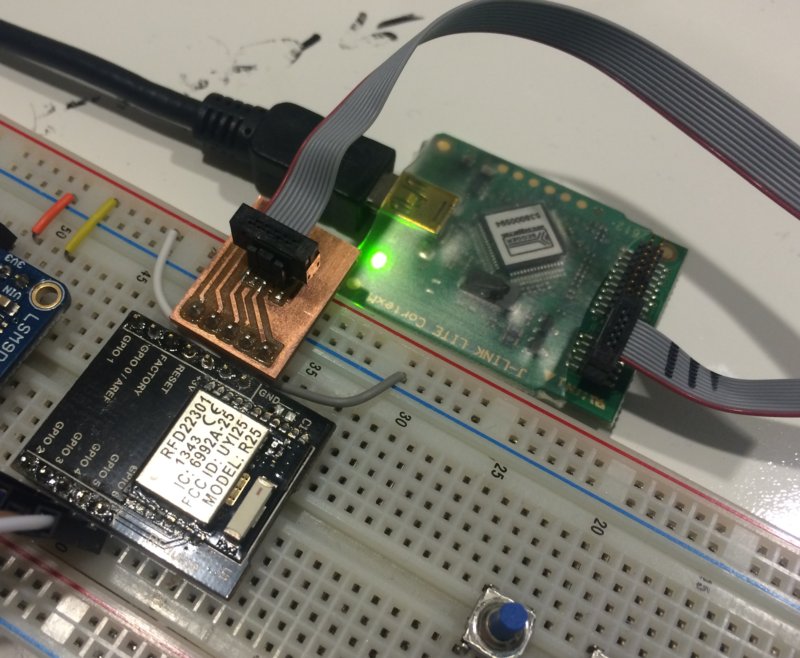
This is a breakout board to connect a J-Link LITE CortexM-9 to a breadboard.
Specifically it breaks out the SWDIO and SWCLK pins on the 9-pin Samtec FTSH-105-01-L-DV-K header to a 5-pin 0.100" header you can plug into a breadboard. The pins are ordered so you can place it right next to an RFDuino and program the Nordic chip directly, bypassing the Arduino environment.
WARNING: There's no going back once you've erased the RFDuino bootloader. From then on you will need to program it directly using the J-Link (or through your own bootloader if you write one.
I designed the board in KiCad, so you'll find here the project files, as well as the exported Gerbers and GCode files that you can use to mill the boards.
I make no guarantees as to the suitibility or quality of these files, and particularly you should check over the GCode files to make sure the settings are good for your particular milling machine.
Mostly this project was a chance to get a smooth workflow together for milling PCBs, so I want to document here what I did. This isn't a schematic capture or PCB layout tutorial, so I'll assume you have designed a board that you now want to mill. Any PCB layout software can export gerbers, so that will be our starting point.
There's a bug with the released version of pcb2gcode where multi-pass path generation seems to use too-small a bounding box, so the outside of traces near the edge don't get enough clearance. You can download my fork from Github until the fix gets merged into master.
This project has a makefile that will generate g-code using pcb2gcode. I encourage you to copy this Makefile, tweak the values, and incorporate it into your own project. The main values that should change project-to-project are all defined at the top of the Makefile. You should check the settings within the individual target rules to make sure they're OK for your machine.
The drill file handling is set up to mill out holes if they're larger than your milling head. We typically use a 1/32" milling head for cutting board outlines and holes, which is a fine diameter for a lot of through-hole components like resistors, but is too small for larger components like header pins. This setting makes it really easy to mill out larger holes automatically, using the diameters listed in your drill file.
This should get you front.ngc, outline.ngc, and drill.ngc, which you can feed into your CNC running software of choice.
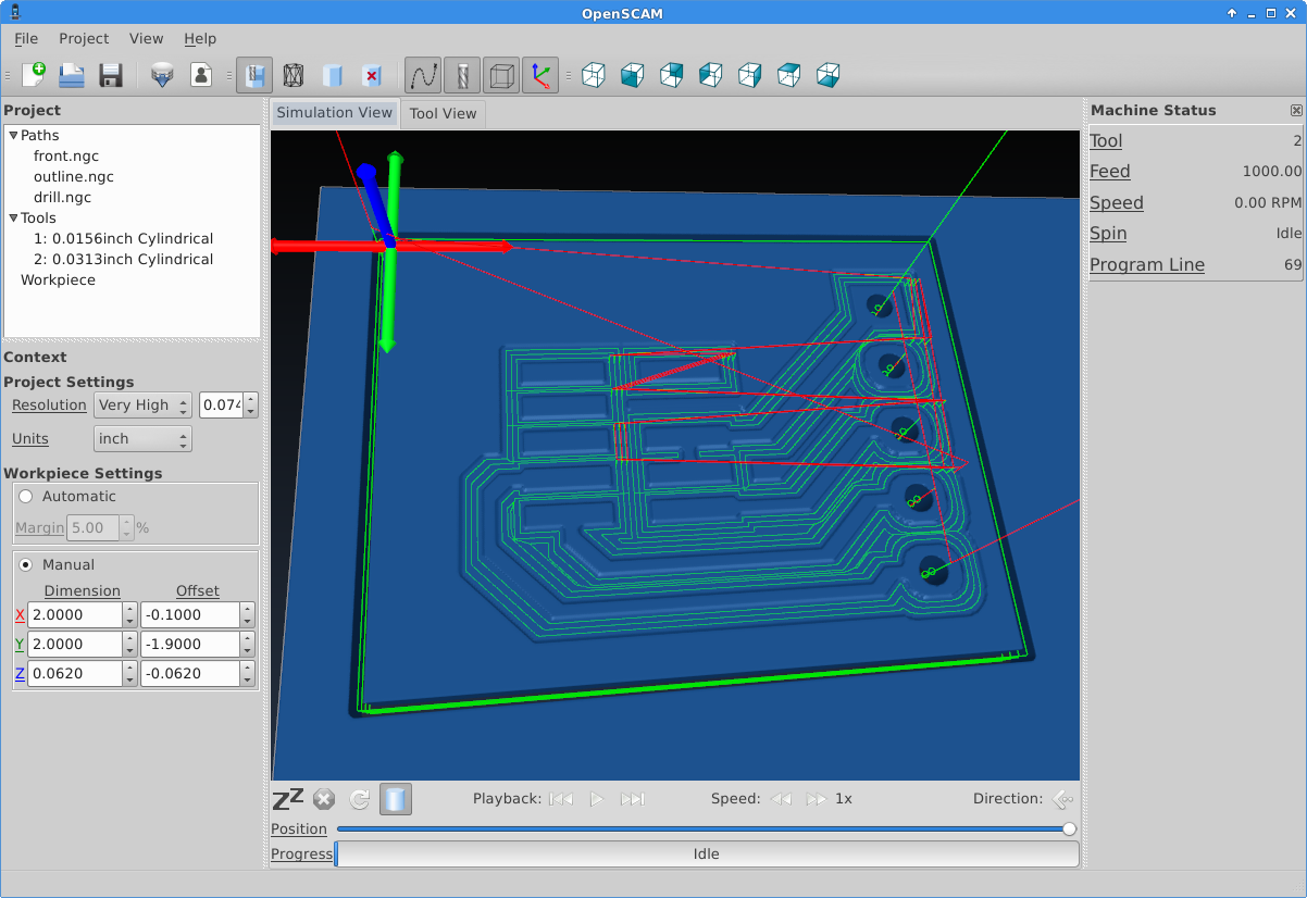
I use OpenSCAM, which is a great open-source gcode
viewer that even simulates what the end product will look like after the
milling is complete. The file ftsh_breakout_openscam.xml is a project file
that includes our gcode files and tool sizes, so you see what the end product
will look like.
Load each gcode file into Mach3, attach the correct milling head, and go to town.
NOTE: Make sure you start the spindle on your CNC before running the gcode for
the drill file! It seems that the generated gcode doesn't have the M3 command
that actually starts the spindle, so you run the risk of running a stationary
bit into your PCB, which is basically guaranteed to break the bit.