Camera Calibrabion PVR is a Blender add-on for matching the 3D camera to the perspective seen in a given photograph. A view of a rectangle in the image is required for this calibration.
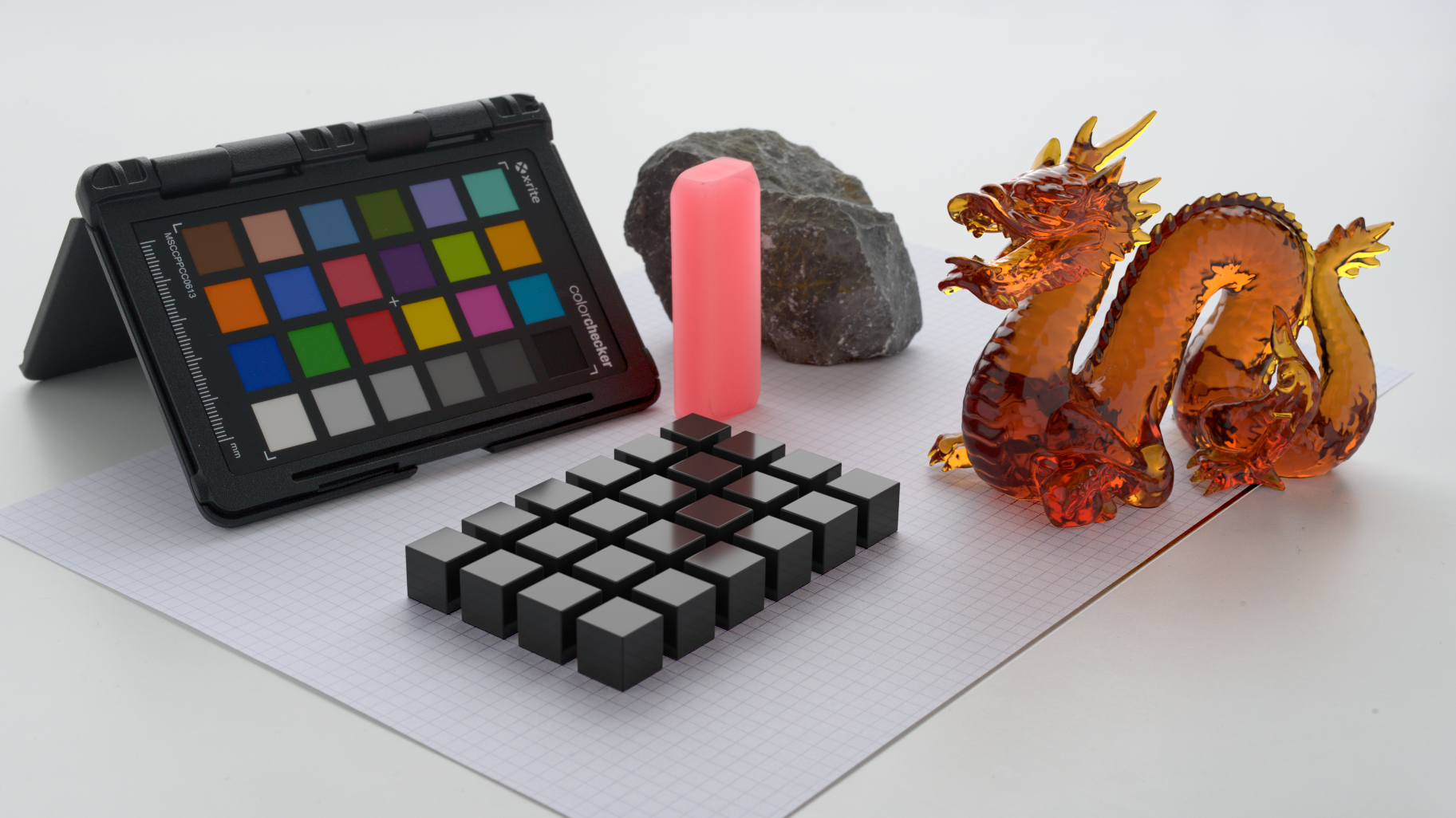
Application example for this add-on. The focal length, position and rotation of the camera used to take this photograph is determined from a rectangle (grid paper). The dragon (credit: Stanford University) and the array of cubes are rendered on top of the image using the calculated perspective.
Link to Blender Artist page
- Download the latest release or clone the repository into a directory of your convenience.
- If you downloaded the zip file, extract it.
- Open Blender.
- Go to File -> User Preferences -> Addons.
- At the bottom of the window, chose Install From File.
- Select the file
camera-calibration-pvr.pyfrom the directory into which you cloned/extracted the repository. - Activate the checkbox for the plugin that you will now find in the list.
- From startup the panel is located in the TOOLS panel, you can change this in the preference in the addon panel.

There are three modes that can be used to calibrate the camera:
- Solve Focal: Uses the image of a single rectangle to calibrate the camera. This is the mode most often used. However, it does not work if the photograph was taken with a tilt-shift lens and/or was cropped. Furthermore, it can not be used if any two edges of the rectangle appear parallel in the image.
- Solve Focal+Y: This is a special mode often used for architectural images where a tilt-shift lens was used. This mode assumes the lens was set up in such a way that vertical lines appear vertical in the image. Therefore, the reference rectangle is required to have exactly two parallel edges.
- Solve Focal+X+Y: This is the more general mode that allows for shift in both vertical and horizontal direction. This is often useful when the image was cropped. The rectangle used for reference may not have any parallel edges.
Perform the following steps:
- Change the 3D view into Top Ortho mode (Top view in Orthographic View mode: press
Numpad 7, thenNumpad 5). - Load a background image for the 3D View by the 3D view properties (on the right side of the 3D view, after pressing
N). Ensure that the image is visible from top view by using either the option All Views or Top. - Optional: Got to wireframe mode (press
Z) - Create a new Plane (
Shift-A-> Mesh -> Plane). - Enter Edit mode (
Tabkey) and move the plane vertices to the corners of the rectangle in the background image. - Leave Edit mode (
Tabkey). - Ensure that the plane is selected. In the 3D view tools (on the left side of the 3D view), select the Tools tab and find the Camera Calibration PVR menu. Press Solve Focal.
This sets the position, the rotation and the focal length of the camera. The view changes automatically to the camera and a new object is created that represents the reconstructed rectangle. By design, this rectangle is parallel to the x-y-plane, at the 3D cursor location. (This can be changed in an option, see below.) The name of the reconstructed rectangle is the one of the original plane, with "_Cal" appended.
Warning: If the background image is set to 'Top' mode, then it will not be visible in camera view. It can safely be changed after the calibration. Also, the original plane may obstruct the view of the reconstructed rectangle when not in wireframe mode. The original plane can be hidden or deleted to make the new plane visible.

To reposition, rotate and/or scale the generated rectangle, be sure to reposition, rotate and/or scale the camera along with it. Also, see the options below.
Vertical lens shift means that the optical centre is not in the centre of the image, but shifted in vertical direction. This can happen when using a tilt-shift lens on a camera or when cropping the image. The algorithm used to make calibrations in this case has two restrictions:
- The rectangle used for calibration needs to have two edges that are parallel
- The shift may only be along vertical direction in the image.
This applies very often in architectural photographs.
To perform the calibration, go through the following steps:
- Change the 3D view into Top Ortho mode (Top view in Orthographic View mode: press
Numpad 7, thenNumpad 5). - Load a background image for the 3D View by the 3D view properties (on the right side of the 3D view, after pressing
N). Ensure that the image is visible from top view by using either the option All Views or Top. - Optional: Got to wireframe mode (press
Z) - Create a new Plane (
Shift-A-> Mesh -> Plane). - Enter Edit mode (
Tabkey) and move the plane vertices to the corners of the rectangle in the background image. - Select one of the vertices and extrude it by pressing
E. Position it as shown in the image below. The edge must be perpendicular in the image in order to be suitable. - Leave Edit mode (
Tabkey). - Ensure that the plane is selected. In the 3D view tools (on the left side of the 3D view) select the Tools tab and find the Camera Calibration PVR menu. Press Solve Focal+Y.

Calibration of focal length, horizontal and vertical lens shift, position and rotation (Solve Focal+X+Y)
Lens shift means that the optical centre is not in the centre of the image, but shifted off-centre. This can happen when using a tilt-shift lens on a camera or when cropping the image.
To perform the calibration, go through the following steps:
- Change the 3D view into Top Ortho mode (Top view in Orthographic View mode: press
Numpad 7, thenNumpad 5). - Load a background image for the 3D View by the 3D view properties (on the right side of the 3D view, after pressing
N). Ensure that the image is visible from top view by using either the option All Views or Top. - Optional: Got to wireframe mode (press
Z) - Create a new Plane (
Shift-A-> Mesh -> Plane). - Enter Edit mode (
Tabkey) and move the plane vertices to the corners of the rectangle in the background image. - Select one of the vertices and extrude it by pressing
E. Position it along a line that is perpendicular to the rectangle. - Repeat the last step for another vertex.
- Leave Edit mode (
Tabkey). - Ensure that the plane is selected. In the 3D view tools (on the left side of the 3D view) select the Tools tab and find the Camera Calibration PVR menu. Press Solve Focal+X+Y.
There are options to the camera calibration:
- Size determines the size of the reconstructed rectangle.
- Vertical orientation places the reconstructed rectangle in vertical orientation instead of parallel to the x-y-Plane.
Here are screen casts that demonstrate the usage.


You should be aware of a few things when using this add-on.
- Solve Focal: Images used for camera calibration should have the optical centre in the centre of the image. This means that cropping the image unevenly or using tilt-shift lenses will make the add-on fail to work. Solve Focal+Y: See the restrictions above.
- Scaling of the image prior to the use for calibration should be done only if the aspect ratio of the image is preserved.
- Lens distortion effects will negatively affect the result.
- Higher image resolution is beneficial to the accuracy of the calibration.
- Rectangles in the image used for calibration should be distorted by perspective. Solve Focal, Solve Focal+X+Y: The more parallel the sides of the rectangles appear in the image, the worse the result. Completely parallel sides will not work. (See also Solve Focal+Y.)
- Right angles in the real world are often not perfect.
- Improved the add-on preferences
- Moved the tool location from the "Misc" tab to the "Tools" tab in the Tool shelf. The location can be configured now.
- The scene name is not hard coded anymore.
- Added an algorithm for calculating vertical and horizontal lens shift along with focal length, position and rotation of the camera. Additional information is taken from two dangling vertices in the mesh.
- Separate button for the new calibration method.
- Renaming of the calibration methods.
- Added an algorithm for calculating vertical lens shift along with focal length, position and rotation of the camera. Additional information is taken from one dangling vertex in the mesh. The rectangle in the image is required to have one pair of parallel edges.
- Separate button for the new calibration method.
- Adding a camera to the scene when none exist.
- Bugfixes
First official release. It includes the following features:
- Algorithm to calculate focal length, position and rotation for the camera used to make a picture of a rectangle.
- The image used for calibration is taken from the viewport background from Top View.
- A mesh of four vertices in one polygon is used to determine the coordinates of the rectangle corners.
- A button in the tool shelf performs the calibration when the mesh is selected.
- A new rectangle is created during the calibration which represents the undistorted rectangle in the image.
- The active camera is transformed according to the calculation results.
- The view automatically changes to camera view.
- Options for the calibration are:
- the size of the reconstructed rectangle
- vertical alignment of the reconstructed rectangle
Camera Calibration with Perspective Views of Rectangles
Copyright (C) 2017 Marco Rossini
This program is free software; you can redistribute it and/or modify it under the terms of the GNU General Public License version 2 as published by the Free Software Foundation.
This program is distributed in the hope that it will be useful, but WITHOUT ANY WARRANTY; without even the implied warranty of MERCHANTABILITY or FITNESS FOR A PARTICULAR PURPOSE. See the GNU General Public License for more details.
You should have received a copy of the GNU General Public License along with this program; if not, write to the Free Software Foundation, Inc., 51 Franklin Street, Fifth Floor, Boston, MA 02110-1301, USA.
This Blender plugin is based on the research paper "Recovery of Intrinsic and Extrinsic Camera Parameters Using Perspective Views of Rectangles" by T. N. Tan, G. D. Sullivan and K. D. Baker, Department of Computer Science, The University of Reading, Berkshire RG6 6AY, UK, from the Proceedings of the British Machine Vision Conference, published by the BMVA Press.